Self-guiding threaded fastener

a threaded fastener and self-guiding technology, applied in the field of fixing orthopedic implants, can solve the problems of weakened engagement between the fastener and the plate, undesirable cross-threading, and inability to optimize the engagement between the screw and the orthopedic plate, so as to facilitate the threading process and avoid cross-threading

Active Publication Date: 2006-06-01
STRYKER EURO OPERATIONS HLDG LLC
View PDF63 Cites 65 Cited by
  • Summary
  • Abstract
  • Description
  • Claims
  • Application Information

AI Technical Summary

Benefits of technology

[0007] A fastener in accordance with the present invention can be used as a monoaxial fastener in a plate or other device having an aperture with a female thread. In one aspect of the present invention, the fastener includes a single thread, the profile which is the same throughout the length of the fastener from the trailing end or proximal end at the bottom of the head (if there is a head) to the leading end or distal end of the fastener. Preferably, the pitch and depth of the thread is the same. However, that portion of the shank of the screw fastener—i.e., the plate engaging portion of the shank—has a different thickness than the remaining shaft of the screw fastener. More specifically, in this embodiment of the invention, the root diameter of the fastener shank (the thickness of the shank without the threads) is larger in the plate engaging portion, and this plate engaging portion is sized to lock with the plate as the bone engaging portion threads into the bone. In a preferred embodiment, there is no taper from the bone engaging portion to the plate engaging portion of the fastener shank. At most, there may be a chamfered step from one portion to the second portion. Preferably, the bone engaging portion of the fastener shank is sized to permit the thread to fit loosely between the female threads of the plate throughout the bone engaging portion of the shaft. This facilitates the threading process and avoids cross-threading.

Problems solved by technology

Since many screws are designed to specifically have threads which are best adapted for anchoring in bony material, often the engagement between the screw and the orthopedic plate is not optimized.
However, instead, as the conical threads become progressively larger and engage the female threads in the apertures of the orthopedic plate, undesirable cross-threading occurs.
This results in a situation where the fastener and the fastener engagement with the plate is weakened.
It may also impede the insertion of the screw fastener as the cross-threading may block the passage of the screw.
The consequences of such cross-threading, whether full threading was possible or not, is that the screw will be very difficult if not impossible to remove from the plate.
Quite often, that aperture of the plate in which the screw fastener is cross-threaded, is destroyed and rendered unavailable for use with another screw fastener.

Method used


Image

  • Self-guiding threaded fastener
  • Self-guiding threaded fastener
  • Self-guiding threaded fastener

Examples


Embodiment Construction

[0034] For the purposes of promoting and understanding the principles of the present invention, reference will now be made to the embodiment illustrated in the drawings and specification language will be used to describe the same. Nevertheless, by those skilled in the art, it will be understood that no limitation of the scope of the present invention is hereby intended and, further, changes in the illustrative device may be made to the preferred embodiments disclosed herein without deviating from the scope of the present invention.

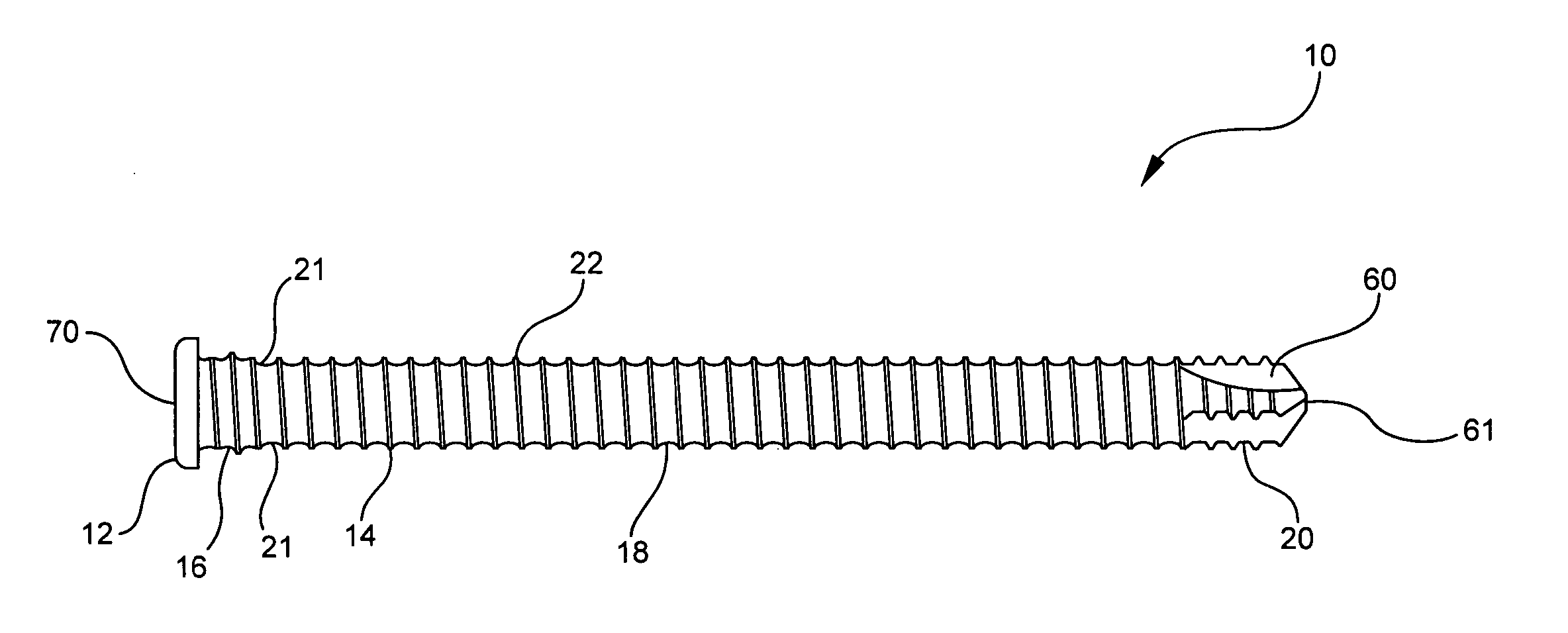
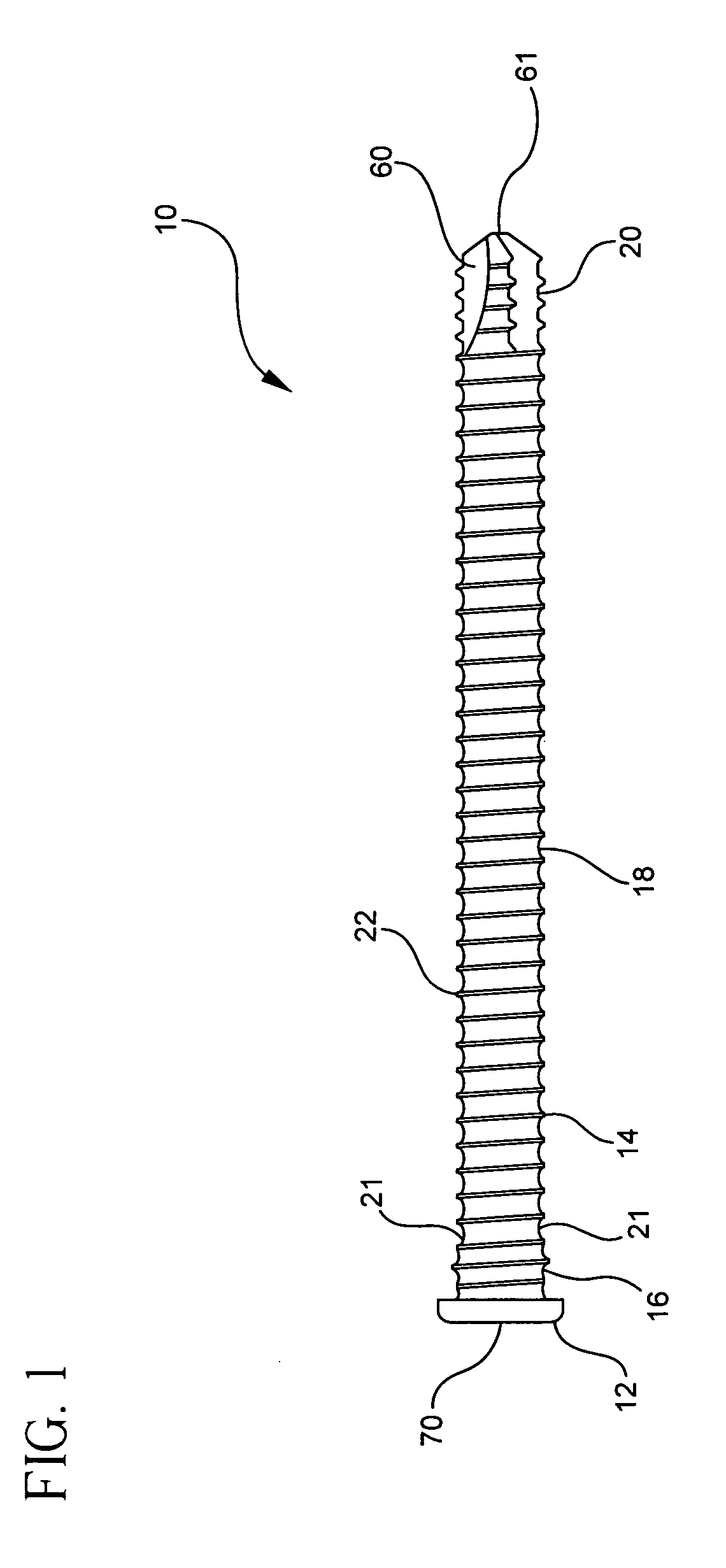
[0035] As shown in FIG. 1, one embodiment of bone screw 10 includes a head 12 and a shank 14. Shank 14 extends downwardly from head 12 and preferably includes first portion 16, second portion 18 and distal tip 20. Shank 14 also preferably includes thread 22 extending radially outward from shank 14. Thread 22 extends radially outward from shank 22 as well as substantially continuous from the proximal end of first portion 16 to distal tip 20.

[0036] As is e...


PUM


Abstract

A screw fastener for attachment to an orthopedic component such as an orthopedic plate for use in connection with fracture fixation, joint reconstruction or spinal stabilization or fusion is disclosed as having a shank with at least two different shank diameters, one in a plate engaging portion of the shank and one in the bone or other component engaging portion of the shank. At least two of the different shank diameters on the shank include threads, the threads on the two different diameter portions each having substantially the same thread height and pitch. A plate having a threaded aperture, or an adapter having a threaded aperture, is sized such that the threads of the smaller diameter shank portion engage and cooperate with the internal threads of the aperture to correctly align the screw fastener and the implant as the screw fastener is threaded through the implant. The threads on the larger diameter shank portion and the internal threads of the aperture of the implant are sized so that the threads of the larger diameter shank portion are fully engaged with the internal threads of the orthopedic implant.

Description

BACKGROUND OF THE INVENTION [0001] The present invention relates to the fixation of orthopedic implants, including fasteners to bones and other orthopedic devices and fasteners for effecting such fixation, as well as associated methods. [0002] Orthopedic surgery, whether it be for fracture fixation, joint reconstruction, spine stabilization or fusion, often comprises the fastening of an implant, including an orthopedic plate, to a bone or to another implant or component of a trauma, reconstructive or fusion system. Typically, a screw fastener is used in conjunction with an aperture in an orthopedic implant, and the threads of the screw fastener engage bone or another component of the system as indicated above. In some cases, particularly with respect to certain orthopedic implants that are to be fixed to a bone to treat a fracture, to aid in joint reconstruction or to aid in stabilization or fusion of vertebral bodies, the screw fastener would include not only threads to engage the ...

Claims


Application Information

Patent Timeline
Patent Type & Authority Applications(United States)
IPC IPC(8): A61B17/58
CPCA61B17/8057A61B17/863A61B17/8685
Inventor CROZET, YVES
Owner STRYKER EURO OPERATIONS HLDG LLC
Why Eureka
Try Eureka