Fan motor noise reduction device and vacuum cleaner with the same

a technology of noise reduction device and vacuum cleaner, which is applied in the direction of carpet cleaners, liquid fuel engines, bowling games, etc., can solve the problems of increasing the manufacturing cost of the motor, unable to meet the consumer's requirements, and large amount so as to achieve remarkable reduction of noise generated by the fan motor of the vacuum cleaner

Inactive Publication Date: 2006-06-08
LG ELECTRONICS INC
View PDF14 Cites 14 Cited by
  • Summary
  • Abstract
  • Description
  • Claims
  • Application Information

AI Technical Summary

Benefits of technology

[0010] It is an object of the present invention to provide a noise reduction device for a vacuum cleaner, which can reduce the noise by preventing the noise from being transmitted to an external side of the vacuum cleaner, thereby reducing an amount of noise transmitted to a user.
[0013] In another aspect of the present invention, there is provided a vacuum cleaner comprising: a fan motor receiving air through a front portion and exhausting the air in a radial direction; a main body receiving the fan motor; a wheel provided on a lower portion of the main body to allow the main body to smoothly move; a flexible connecting hose extending from the main body; a suction nozzle directing outer air to the connecting hose by contacting a flour bottom; a casing enclosing the fan motor, the casing being provided with an air hole through which the air passes and expands to reduce noise; and a sound absorption member provided on an inner and / or outer portion of the casing.
[0016] According to the present invention, noise generated from the fan motor of the vacuum cleaner is remarkably reduced.

Problems solved by technology

When the vacuum cleaner is operated, a large amount of noise is generated.
The noise is generally caused by friction between parts of the fan motor, collision between the fan and the air, and airflow.
However, the former has a problem in that the manufacturing cost of the motor is increased.
However, these cannot satisfy the consumer's requirements.

Method used


Image

  • Fan motor noise reduction device and vacuum cleaner with the same
  • Fan motor noise reduction device and vacuum cleaner with the same
  • Fan motor noise reduction device and vacuum cleaner with the same

Examples


Embodiment Construction

[0024] Reference will now be made in detail to the preferred embodiments of the present invention, examples of which are illustrated in the accompanying drawings. Wherever possible, the same reference numbers will be used throughout the drawings to refer to the same or like parts.

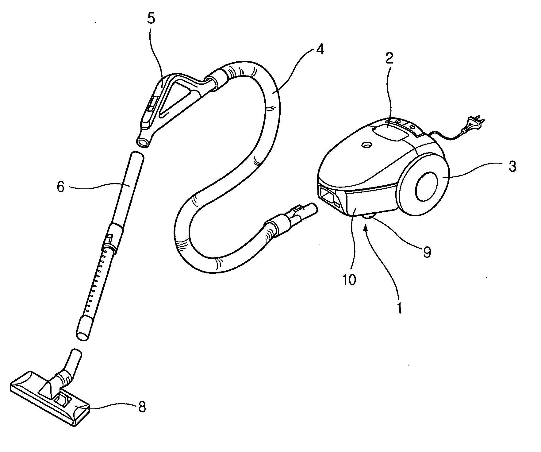
[0025]FIG. 1 shows a perspective view of a vacuum cleaner according to an embodiment of the present invention.

[0026] Referring to FIG. 1, the inventive vacuum cleaner includes a main body 1 having a lower cover 10 with a fan motor, a flexible connecting holes 4 communicating with an interior side of the main body 1, an extendable tube 6 connected to the connecting holes 4, and a suction nozzle 8 coupled to an end of the extendable tube 6 to suck foreign objects by contacting a flour. Main wheels 3 and sub-wheels 9 are installed on a bottom of the main body 2 to direct the vacuum cleaner to a desired direction.

[0027] In order to move the cleaner to another place while using the cleaner, the user grasps a ...


PUM


Abstract

A vacuum cleaner includes a fan motor generating air current, a main body receiving the fan motor, a wheel allowing the main body to smoothly move, a flexible connecting hose extending from the main body, an expandable extending tube connected to the connecting holes, a suction nozzle connected to an end of the extending tube to suck outer air, an inner sound absorption member disposed around the fan motor to absorb noise generated by the fan motor, a casing disposed around the inner sound absorption member to enclose the fan motor, the casing being provided with an air hole through which the air is exhausted in a side direction of the fan motor, and an outer sound absorption member disposed around the casing to absorb the noise generated by the fan motor.

Description

BACKGROUND OF THE INVENTION [0001] 1. Field of the Invention [0002] The present invention relates to a fan motor noise reduction device for a vacuum cleaner, and more particularly, to a fan motor noise reduction device that can reduce the noise of a vacuum cleaner by preventing the noise generated in the fan motor from being transmitted out of the fan motor. [0003] 2. Description of the Related Art [0004] Generally, a vacuum cleaner is a device for collecting foreign objects such as dusts in a dust bag using powerful suction force of a fan motor. [0005] A prior vacuum cleaner includes a nozzle unit to which outer air is introduced and a cleaner body through which the outer air introduced into the nozzle unit is exhausted after foreign objects contained in the outer air are filtered out. The cleaner body receives a fan motor comprised of a suction fan and a motor that are integrated in a single body. The suction fan functions to generate suction force for allowing outer air to be for...

Claims


Application Information

Patent Timeline
Patent Type & Authority Applications(United States)
IPC IPC(8): A47L5/00
CPCA47L9/0081A47L9/00A47L9/22
Inventor HWANG, JUNG BAI
Owner LG ELECTRONICS INC
Why Eureka
Try Eureka