Suction muffler for a hermetic compressor

a compressor and suction muffler technology, which is applied in the direction of positive displacement liquid engines, shock absorbers, cable terminations, etc., can solve the problems of high manufacturing cost, high manufacturing cost, and inability to ensure the necessary tightness of the suction muffler. the effect of low cos

Inactive Publication Date: 2006-06-08
EMPRESA BRASILEIRA DE COMPRESSORES SA (EMBRACO)
View PDF22 Cites 11 Cited by
  • Summary
  • Abstract
  • Description
  • Claims
  • Application Information

AI Technical Summary

Benefits of technology

[0011] Thus, it is an object of the present invention to provide a system for closing a suction muffler of a hermetic compressor of low cost and without presenting the deficiencies of the known prior art solutions.

Problems solved by technology

On the other hand, the suction muffler means load loss for the gas flow being drawn.
The solutions that use welding are not generally satisfactory, since they allow the occurrence of excess welding material in the joining region of the parts of hollow base and cover, which is mainly prejudicial when said excess occurs in the interior of the suction muffler, since it interferes with the gas flow therein and does not guarantee the necessary tightness to the suction muffler.
The solutions using metallic or plastic clamps, as well as those using adhesives or insertion of material between the hollow base and the cover, have as disadvantages the high manufacturing cost and the fact of not guaranteeing the necessary tightness to the suction muffler.
While solving the deficiencies of the techniques mentioned above, such constructions are susceptible to breaks and / or disengagements caused for example by impacts, fatigue or thermal variations, impairing the operation of the compressor.

Method used


Image

  • Suction muffler for a hermetic compressor
  • Suction muffler for a hermetic compressor
  • Suction muffler for a hermetic compressor

Examples


Embodiment Construction

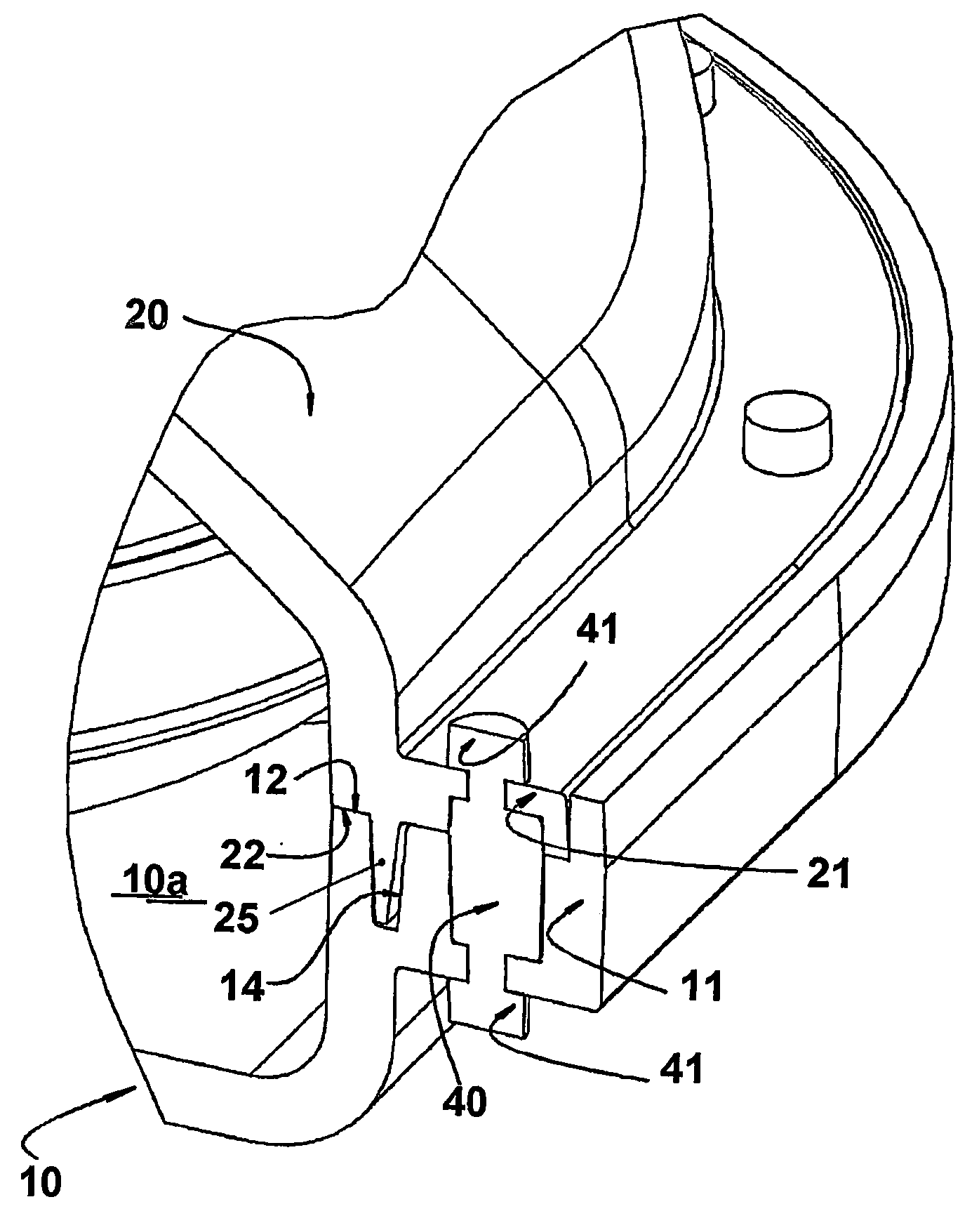
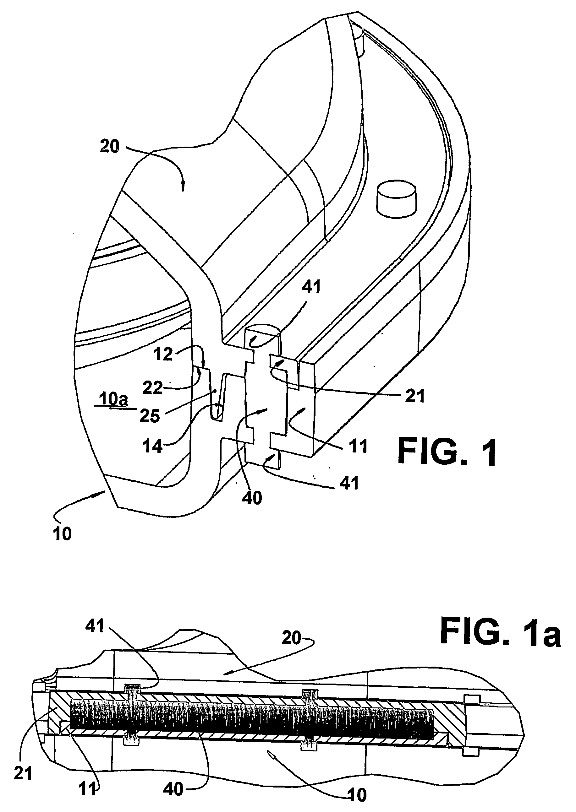
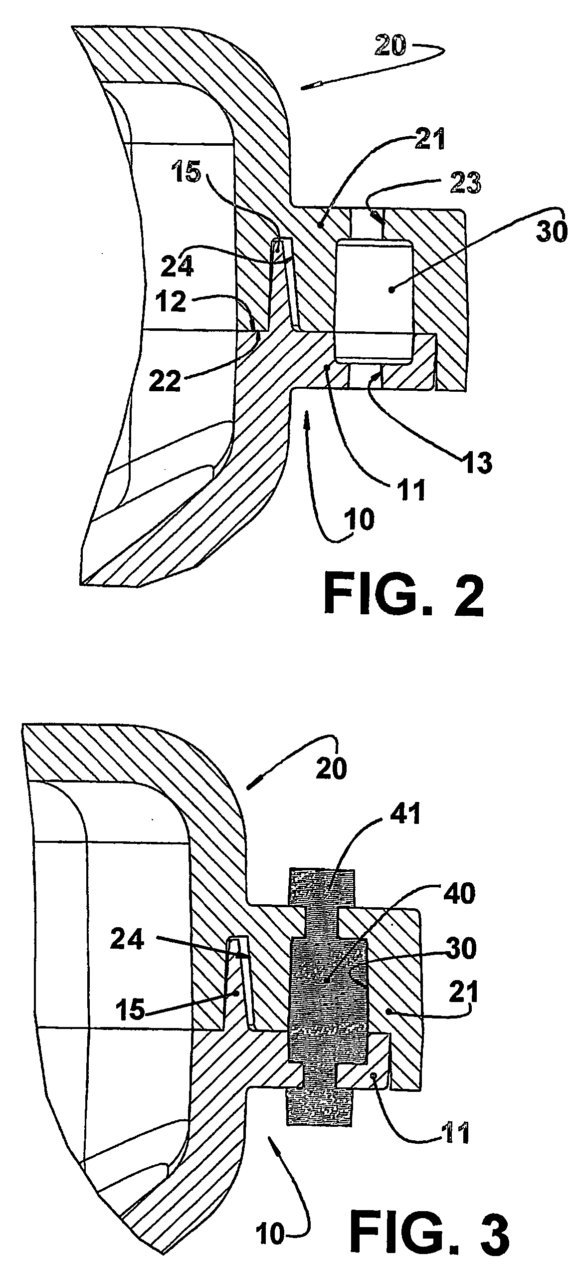
[0022] The present invention will be described in relation to a suction muffler of the type used in a hermetic compressor of a refrigeration system and which, though not illustrated, comprises, inside a hermetic shell, a motor-compressor assembly having a cylinder block within which is defined a cylinder, lodging at one end, a piston, and having an opposite end closed by a cylinder cover which defines, in its interior, a housing to receive the suction muffler, and a discharge chamber in selective fluid communication with a compression chamber defined inside the cylinder, between a top portion of the piston and a valve plate provided between the opposite end of the cylinder and the cylinder cover through suction and discharge orifices provided in said valve plate and which are selectively and respectively closed by suction and discharge valves.

[0023] According to the illustrations, the gas being drawn by the compressor and coming from a suction line of the refrigeration system opene...


PUM

PropertyMeasurementUnit
circumferential distanceaaaaaaaaaa
thermal insulationaaaaaaaaaa
volumesaaaaaaaaaa

Abstract

A system for closing a suction muffler of a hermetic compressor, the suction muffler including: a hollow base; a cover to be coupled to the hollow base, the parts defined by the hollow base and the cover including respective mutually seatable peripheral flanges, which are shaped to define, jointly, an internal channel extended along at least part of the circumferential extension of the peripheral flanges and which is opened to the opposite external faces of the latter by means of throughbores axially aligned to each other in pairs, each pair of throughbores maintaining a circumferential distance in relation to an adjacent pair of throughbores, the throughbores of each pair and the internal channel being filled with a gasket of injected material, which projects outwardly from the throughbores so as to define an axial lock portion

Description

FIELD OF THE INVENTION [0001] The present invention refers to a system for closing a suction muffler of a compressor of the type used in refrigeration machines, such as refrigerators, freezers, water fountains, refrigerated counters, etc. BACKGROUND OF THE INVENTION [0002] The hermetic compressors of refrigeration systems have their suction usually provided with an acoustic dampening system (acoustic filter or suction muffler), mounted in the interior of the shell and which conducts the gas coming from the suction line to the suction valve. [0003] The suction muffler performs several functions that are important to the good operation of the compressor, such as gas directioning, acoustic dampening and, in some cases, the thermal insulation of the gas being drawn to the interior of the cylinder. [0004] The suction muffler is generally formed by a sequence of volumes and tubes that conduct the gas coming from the suction line directly to the suction valve. This displacement of the gas ...

Claims


Application Information

Patent Timeline
Patent Type & Authority Applications(United States)
IPC IPC(8): F04B39/00F04B53/00B29C45/00F01N13/18
CPCB29C45/0062F04B39/0072F04B39/0061F04B39/121F05B2210/12F05B2240/57F05B2260/30Y10S181/403Y10S417/902
Inventor VOLLRATH, INGWALDHILLE, CLAUDIO ROBERTO
Owner EMPRESA BRASILEIRA DE COMPRESSORES SA (EMBRACO)
Why Eureka
Try Eureka