Lock-up clutch mechanism

a technology of locking mechanism and clutch, which is applied in the direction of rotary clutch, fluid coupling, gearing, etc., can solve the problems of unbalanced surface pressure distribution, unsatisfactory transmission efficiency, and affecting the comfort of the vehicle, so as to reduce the jadder and improve the uniformity of friction surface pressure in the circumferential direction.

Active Publication Date: 2006-06-08
NSK WARNER
View PDF7 Cites 15 Cited by
  • Summary
  • Abstract
  • Description
  • Claims
  • Application Information

AI Technical Summary

Benefits of technology

[0013] By providing the protruded area protruding in the axial direction on the friction surface, even when a piston of the lock-up clutch is urging with a relatively small urging force during lock-up slip, since contact surface pressure at an apex of the protruded area is high and the friction material can be contacted with the front cover substantially uniformly in a circumferential direction due to flexibility of the friction material, the uniformity of the friction surface pressure in the circumferential direction is improved.
[0014] Further, even if the urging force of the piston is changed, the uniformity of the friction surface pressure in the circumferential direction is maintained more stably, thereby reducing the jadder.

Problems solved by technology

A torque converter used in an automatic transmission can provide smooth start, acceleration and deceleration, but has worse transmitting efficiency since it transmits a power via fluid.
In general, the lock-up clutch may cause self-excited vibration called as jadder, thereby worsening the comfort of the vehicle considerably.
The unbalance of the surface pressure distribution is greatly influenced by accuracy of the friction surface, and, for example, dispersion is generated on the friction surface in the circumferential direction by undulation of a piston of the lock-up clutch and / or distortion of a fitting bolt for a drive plate provided in a front cover.
However, since the occurrence of the jadder greatly relies upon the unbalance of the surface pressure distribution in the circumferential direction at the friction surface during the slipping, the jadder is not necessarily avoided by the technique disclosed in the above-mentioned Japanese Patent Application Laid-open No. 2004-011710.

Method used


Image

  • Lock-up clutch mechanism
  • Lock-up clutch mechanism
  • Lock-up clutch mechanism

Examples


first embodiment

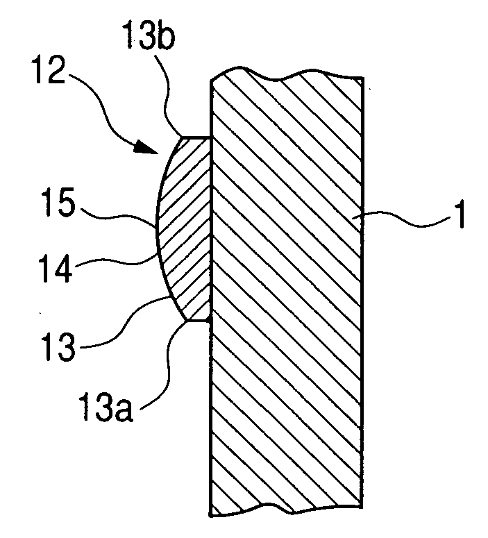
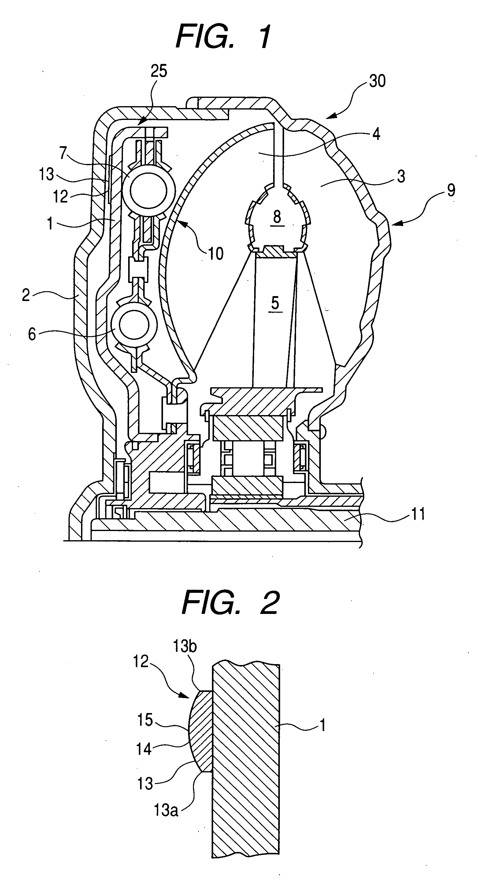
[0026]FIG. 2 is an enlarged partial sectional view showing a piston and a friction material according to a first embodiment of the present invention. The friction material 12 has a protruded area 14 N protruding axially from the friction surface 13. In this embodiment, the protruded area 14 is formed as a curves surface between a radial inner end 13a and a radial outer end 13b of the friction surface 13, and an axial thickness of the friction material 12 becomes maximum at an apex 15 positioned in a substantially central position of the friction material.

[0027] The protruded area 14 is provided through a whole circumferential periphery of the substantially annular friction material 12. A curved surface configuration of the friction surface 13 is formed by a molding process when the friction material 12 is secured to the piston 1. That is to say, an additional process for forming the curved surface configuration is not required.

[0028] In order to manufacture a lock-up clutch mechan...

second embodiment

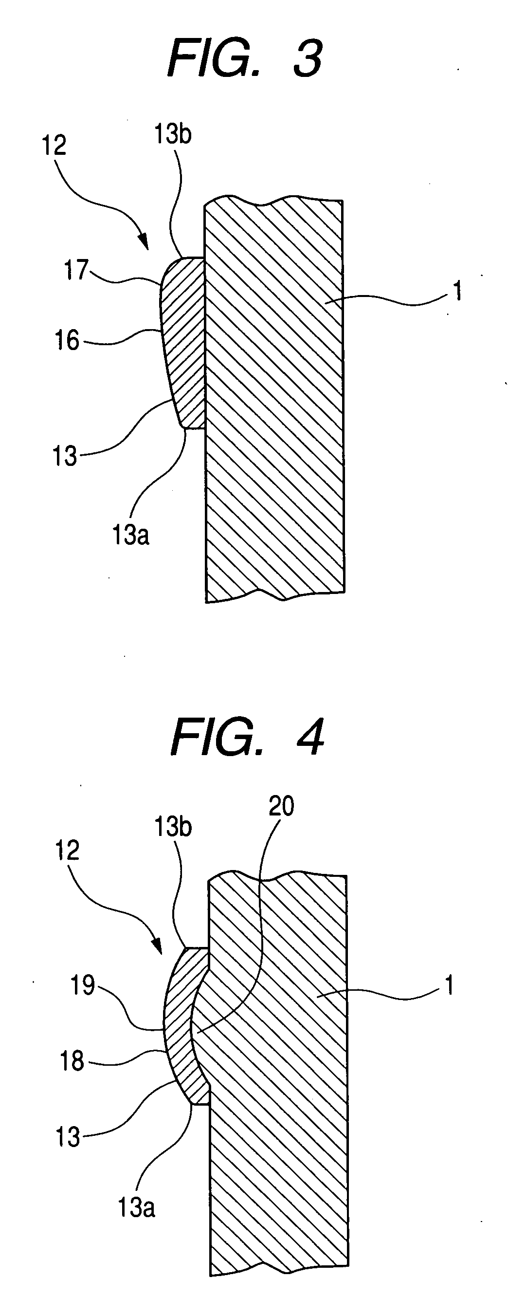
[0029]FIG. 3 is an enlarged partial sectional view showing a piston and a friction material according to a second embodiment of the present invention. The friction material 12 has a protruded area 16 protruding axially from the friction surface 13. Also in this embodiment, the protruded area 16 is formed as a curves surface between a radial inner end 13a and a radial outer end 13b of the friction surface 13. An axial thickness of the friction material 12 becomes greatest at an apex 17 of the protruded area 17. In the illustrated embodiment, the apex 17 is positioned nearer the outer end 13b of the friction material than the inner end 13a, and a region between the apex 17 and the inner end 13a is formed as a curved surface gently inclined.

[0030] Similar to the first embodiment, the protruded area 16 is provided through a whole circumferential periphery of the substantially annular friction material 12. Further, a curved surface configuration of the friction surface 13 is formed by a...

third embodiment

[0032]FIG. 4 is an enlarged partial sectional view showing a piston and a friction material according to a third embodiment of the present invention. The friction material 12 has a protruded area 18 protruding axially from the friction surface 13. In this embodiment, the protruded area 18 is formed as a curves surface between a radial inner end 13a and a radial outer end 13b of the friction surface 13, and an axial protruded amount of the friction material becomes maximum at an apex 19 positioned in a substantially central position of the friction material.

[0033] Similar to the first and second embodiments, the protruded area 18 is provided through a whole circumferential periphery of the substantially annular friction material 12. However, in the third embodiment, different from the first and second embodiments, as apparent from FIG. 4, the friction material 12 is curved but has a substantially uniform thickness.

[0034] In this embodiment, a part-of the piston 1 to which the frict...


PUM

PropertyMeasurementUnit
frictionaaaaaaaaaa
radial outer diameteraaaaaaaaaa
thicknessaaaaaaaaaa

Abstract

The present invention provides a lock-up clutch mechanism for a torque converter, comprising a lock-up clutch to which a friction material having a friction surface is secured and a front cover having an engagement surface with which the friction surface is engaged when the friction surface is urged in an axial direction and in which the friction surface of the friction material has a configuration including a protruded area protruding in the axial direction.

Description

BACKGROUND OF THE INVENTION [0001] 1. Field of the Invention [0002] The present invention relates to a lock-up clutch mechanism used in a torque converter of an automatic transmission for a vehicle and more particularly, it relates to an improvement in a frictional sliding surface of the lock-up clutch mechanism. [0003] 2. Related Background Art [0004] A torque converter used in an automatic transmission can provide smooth start, acceleration and deceleration, but has worse transmitting efficiency since it transmits a power via fluid. Thus, there has been proposed a technique in which, if a speed of a vehicle exceeds a predetermined value, a lock-up clutch mechanism is operated to connect to a drive wheel directly in order to reduce energy loss and enhance a fuel consumption rate. [0005] Further, in recent years, in order to further enhance the fuel consumption rate, the lock-up clutch mechanism has been operated even at a low speed operation of the vehicle. In this case, in order t...

Claims


Application Information

Patent Timeline
Patent Type & Authority Applications(United States)
IPC IPC(8): F16H45/02
CPCF16H45/02F16H2045/0226Y10T29/49F16H2045/0294F16H2045/0289
Inventor FUJII, TAMOTSUMARUO, KENJITAKABAYASHI, HIDEAKI
Owner NSK WARNER
Why Eureka
Try Eureka