Powder compacting apparatus for continuous pressing of pharmaceutical powder

a technology of compacting apparatus and pharmaceutical powder, which is applied in the direction of dough shaping, manufacturing tools, food shaping, etc., can solve the problems of reducing the recompressibility of products, poor control of flow smoothness, and poor control of powder leveling and pressure distribution, so as to facilitate powder flow leveling, facilitate powder passing, and enhance friction surface

Inactive Publication Date: 2007-07-24
ROLAND EDWARD J
View PDF38 Cites 7 Cited by
  • Summary
  • Abstract
  • Description
  • Claims
  • Application Information

AI Technical Summary

Benefits of technology

[0009]The present invention provides a powder compacting apparatus which continuously presses pharmaceutical powder into a compressed material or substrate with optional feedback control to maintain uniformity of the compressed substrate. A main housing is provided which is adapted to receive powder for compacting thereof. The housing includes a powder inlet opening for receiving powder therethrough. The housing also includes a powder flow leveling channel in fluid flow communication with respect to the powder inlet opening for receiving powder therefrom. The powder flow leveling channel can be tapered along at least a partial section therealong to facilitate compacting of powder passing therethrough. The powder flow leveling channel includes an enhanced friction surface therealong to further facilitate powder flow leveling.
[0010]Also defined in the main housing is a powder introduction channel in flow communication with respect to the powder inlet opening for receiving powder therefrom and in fluid flow communication with respect to the powder flow leveling channel for supplying of powder thereto. The powder introduction channel is adapted to guide the movement of powder from the powder inlet opening to the powder flow leveling channel. A nip zone or nip point is defined downstream of the flow leveling zone within the compaction zone immediately upstream from the rollers. The nip zone is the point where there is no further sliding of the powders against the roller surfaces. Here sufficient grip has been achieved to cause the powders to move at the same velocity as the velocity of the circumferential surfaces of the rollers. A first vent is also defined extending from the powder flow leveling channel to the ambient external environment to facilitate release of gases generated. A second vent is also included extending from the powder flow leveling channel to the ambient external environment to facilitate release of gases generated. A porous filter is preferably included located within the first vent to prevent powder from exiting the main housing while allowing gases to exit therefrom.

Problems solved by technology

Current prior art systems and apparatus have significant problems with dry granulation and roller compaction systems.
In particular, there is very poor control of smoothness of flow, powder leveling and pressure distribution.
This inaccurate control often results in uneven compressing or excessive compressing which reduces the recompressability of the product.
Also under compressing presents an entirely different set of problems wherein the final product is not granules, but actual dust due to the lack of sufficient compression.
In the prior art there is no accurate means for allowing full measurement and control of compacting pressure and distribution.
Many machine designs have been made for the purpose of testing, however, these normally are small quantity test materials, and the results are often not reproducible or predictable when scaled up to a full size machine usable in a production line.

Method used


Image

  • Powder compacting apparatus for continuous pressing of pharmaceutical powder
  • Powder compacting apparatus for continuous pressing of pharmaceutical powder
  • Powder compacting apparatus for continuous pressing of pharmaceutical powder

Examples


Embodiment Construction

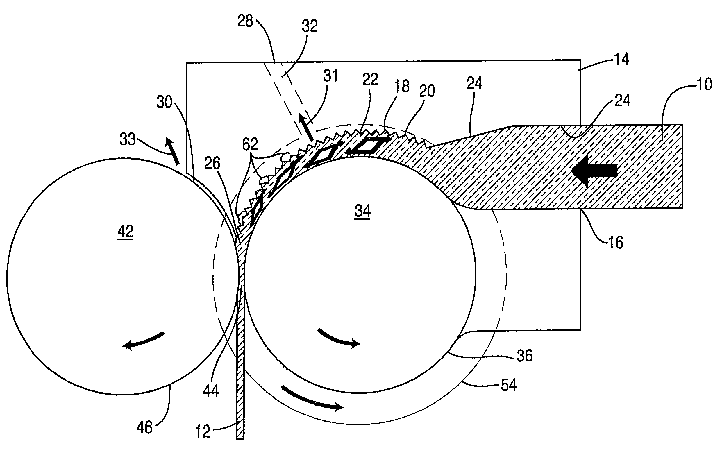
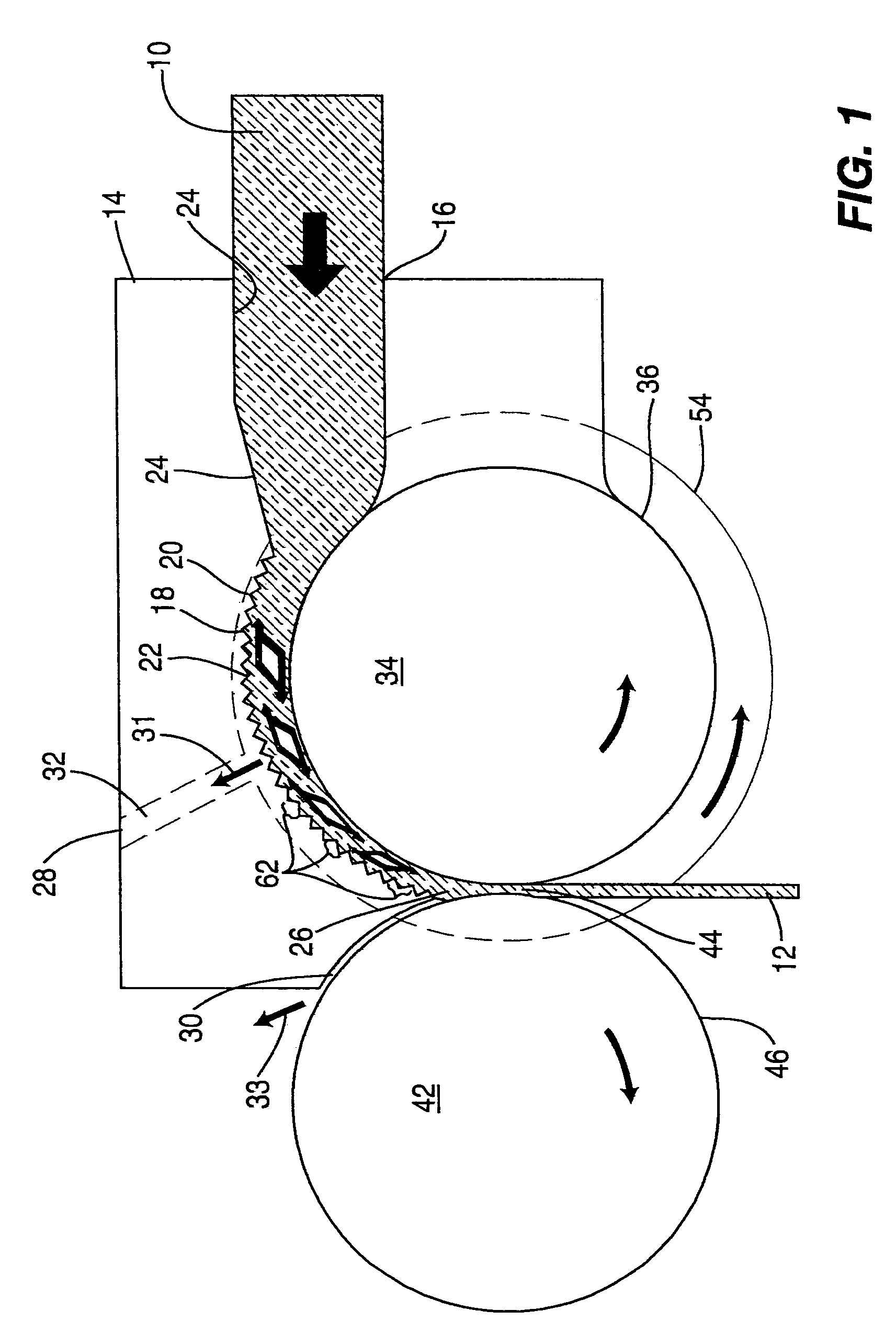
[0035]The apparatus of the present invention is designed for the purpose of receiving powder 10 such as pharmaceutical powder and compressing it into a compressed substrate 12 of material from which pharmaceutical tablets can easily be formed.

[0036]The apparatus includes a main housing 14 which defines a powder inlet opening 16 for receiving powder passing thereinto. A powder introduction channel 24 can optionally be included for transferring or carrying of uncompressed powder from inlet opening 16 to a powder flow leveling channel 18. The powder flow leveling channel 18 can optionally include a tapered section 20 along. Also the main housing 14 will defined an enhanced friction surface 22 within the powder flow leveling channel 18 as shown best in FIG. 1. This irregular surface along the upper portion of the powder flow leveling channel 18 defined at the powder introduction channel 24 is shown in an exaggerated manner in FIG. 1. Also, a nip zone 26 is defined within the roller comp...


PUM

PropertyMeasurementUnit
rotational movement speedsaaaaaaaaaa
rotational speedaaaaaaaaaa
rotational speedsaaaaaaaaaa

Abstract

Improved powder compacting apparatus for feeding powder between rollers to form a compressed material with enhanced physical properties including uniformity to facilitate forming tablets and similar items therefrom. Side seals confine the powder between the rollers and can be movable independently from the rollers and optionally independently from one another to enhance even compaction. A housing defines a guide channel with a linear feed and shearing zone immediately prior to the nip zone for smoothing and leveling powder flow. One or more vents are provided for releasing gases generated.

Description

[0001]This application claims priority rights of the U.S. Provisional Patent Application No. 60 / 512,269 filed Oct. 20, 2003 on “Improved Roller Compaction Apparatus And Process” by the same inventor, Edward J. Roland, now pending.BACKGROUND OF THE INVENTION[0002]1. Field of the Invention[0003]Pharmaceutical entities use dry granulated material for forming tablets. This powder needs to flow smoothly and uniformly during compaction to facilitate forming of pharmaceutical tablets from the compressed material. Dry granulation is the preferred system since it is an in line process, and is not processed in batches. Instead it is a continuously occurring process which can be monitored. This process provides significantly greater product control. Also such processes minimize gaseous emissions that could otherwise be problematic. Furthermore, there are no solvents which provide various environmental problems. Also, other prior art systems are more complicated, and for this reason, pharmaceut...

Claims


Application Information

Patent Timeline
Patent Type & Authority Patents(United States)
IPC IPC(8): B29C43/46B30B11/00B28B3/12B30B11/18
CPCB30B11/18Y10S425/812
Inventor ROLAND, EDWARD J.
Owner ROLAND EDWARD J
Why Eureka
Try Eureka