Communication system for vehicle, vehicle, and communication device for vehicle

a communication system and vehicle technology, applied in the field of vehicle communication system, vehicle communication equipment, vehicle communication equipment, etc., can solve the problems of increasing the cost, and increasing the cost of equipmen

Inactive Publication Date: 2006-06-08
SONY CORP
View PDF11 Cites 43 Cited by
  • Summary
  • Abstract
  • Description
  • Claims
  • Application Information

AI Technical Summary

Problems solved by technology

Hei 9-51309, because it transmits information between vehicles using a laser beam signal, it must have light emitting/receiving units for emitting a laser beam specific thereto provided at the front and the rear ends of the vehicle, thereby increasing the cost.
Moreover, because this equipment carries out information transmission using the laser beam, if the laser beam emitted from the aforementioned light emitting/receiving unit impinges on a human body,...

Method used


Image

  • Communication system for vehicle, vehicle, and communication device for vehicle
  • Communication system for vehicle, vehicle, and communication device for vehicle
  • Communication system for vehicle, vehicle, and communication device for vehicle

Examples


embodiment 1

(1) Embodiment 1

Communication Equipment for Use Between a Stationary Apparatus and a Vehicle: FIGS. 1 to 8

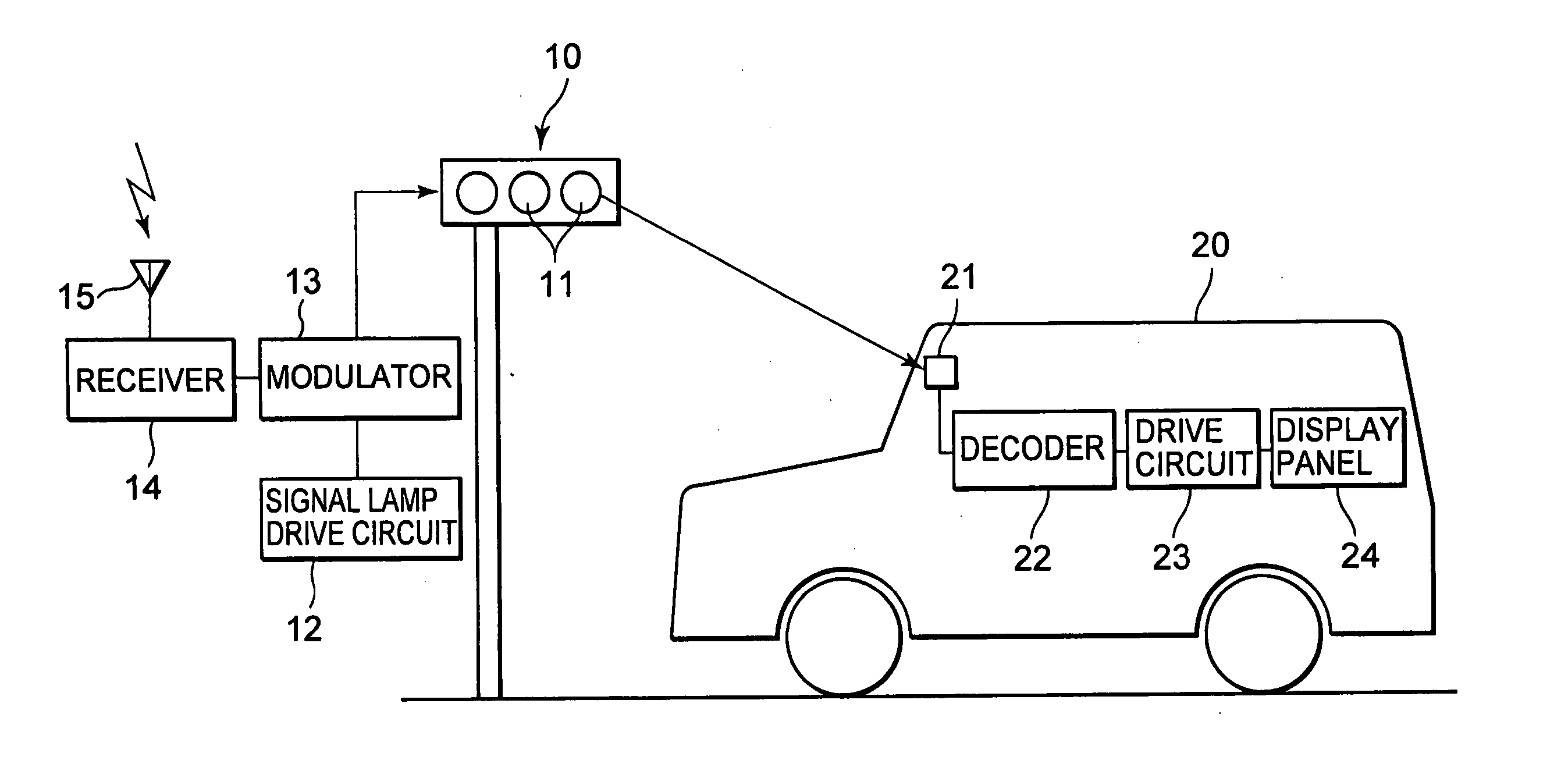
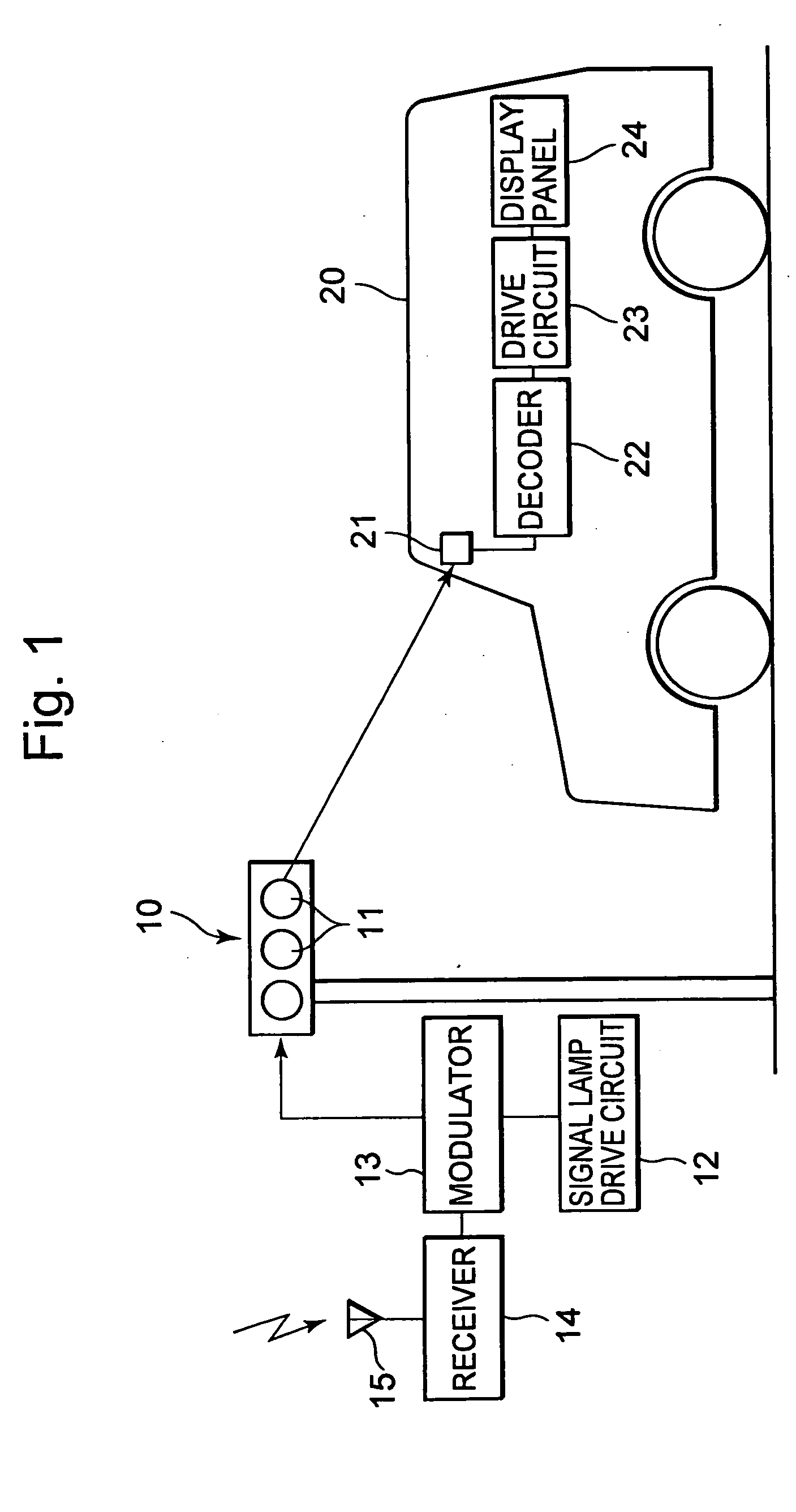
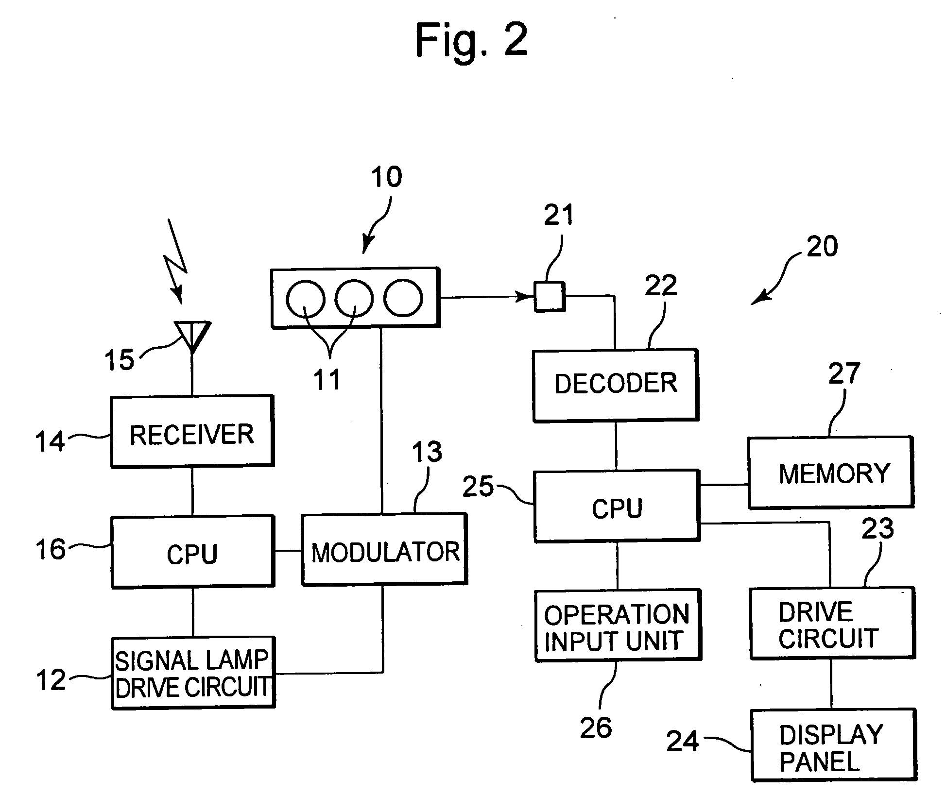
[0048] A typical example of a first embodiment will be described by referring to FIGS. 1 to 4. This equipment is directed to vehicle communication equipment for carrying out information transfer between a traffic signal stationarily installed and a vehicle. As shown in FIG. 1, a traffic signal 10 installed at an intersection of roads or the like has a signal lamp 11 including green, yellow and red colors. A light emitting unit of the signal lamp 11 is comprised, for example, of LEDs (Light Emitting Diodes). This signal lamp 11 is driven by a signal drive circuit 12 which is conventionally known. And a modulator 13 is connected between this drive circuit 12 and the signal lamp 11. The modulator 13 is further connected to a receiver 14. This receiver 14 receives a command signal from outside via an antenna 15.

[0049] Conversely, on the side of a vehicle 20, there are provided a li...

embodiment 2

(2) Embodiment 2

Inter-vehicle Communication Equipment: FIGS. 10 to 16

[0070] This preferred embodiment of the invention is directed to an inter-vehicle communication system for carrying out information transfer between vehicles using light. That is, as shown in FIG. 10, a head lamp 35 and / or a tail lamp 36 already provided on a car are utilized. And a modulator 13 is connected to these lamps 35, 36 for superimposing a signal thereon. Further, a light receiving unit 21 for receiving a light is mounted respectively at a front end and a rear end of a vehicle 20. And these light receiving units 21 are connected to a decoder 22. Further, these lamps 35, 36 preferably use LEDs, xenon lamp or the like as its light source to ensure a good responsiveness to the modulation by the modulator 13.

[0071]FIG. 11 shows a system configuration of such vehicle communication equipment described above, in which the decoder 22 is connected to the light receiving unit 21, and this decoder 22 is also conn...


PUM


Abstract

The present invention is directed to vehicle communication equipment capable of transferring information using light without adding new light emitting means, and further, between a stationary apparatus and a vehicle or between vehicles. A light emitted from a signal lamp (11) of a stationarily installed traffic signal (10) or a head lamp (35) or a tail lamp (36) of a vehicle (20) is superimposed with a signal by a modulator (13), the modulated light is received by a light receiving unit (21) of the vehicle (20) side, and the received modulated light is demodulated by a decoder (22) to be displayed on a display panel (24).

Description

TECHNICAL FIELD [0001] The present invention relates to a vehicle communication system, a vehicle, and vehicle communication equipment, and, in particular, it relates to a vehicle communication system, a vehicle, and vehicle communication equipment that carry out information transfer by using light. BACKGROUND ART [0002] For example, in Japanese Patent Application Publication (KOKAI) No. Hei 9-51309 there is proposed an inter-vehicle communication system, comprising: a forward light emitting / receiving unit for emitting or receiving a laser beam signal to and from a forward direction of a vehicle; a backward light emitting / receiving unit for emitting or receiving a laser beam signal to and from a backward direction of the vehicle; and signal relay means for relaying signals between the forward light emitting / receiving unit and the backward light emitting / receiving unit so that a laser beam signal including a signal received by the forward light emitting / receiving unit is transmitted ...

Claims


Application Information

Patent Timeline
IPC IPC(8): G08G1/00H04B10/00B61L29/24G08G1/09G08G1/095B61L5/18B60Q1/50B61L29/28G08G1/0967G08G1/16H04B10/11H04B10/116H04B10/29
CPCB60Q1/50G08G1/092G08G1/096783G08G1/161G08G1/164B60Q1/5035
Inventor SHINADA, AKIRAMATSUMURA, KENJI
Owner SONY CORP
Why Eureka
Try Eureka