Thermal assist head slider

a technology of head slider and assist head, which is applied in the direction of maintaining head carrier alignment, track selection/addressing details, instruments, etc., can solve the problems of affecting the recording quality of the recording, so as to achieve the effect of small power consumption

Inactive Publication Date: 2006-06-08
WESTERN DIGITAL TECH INC
View PDF11 Cites 16 Cited by
  • Summary
  • Abstract
  • Description
  • Claims
  • Application Information

AI Technical Summary

Benefits of technology

[0026] According to the present invention, the number of connecting lead wires between the magnetic head slider and the suspension is reduced to permit mounting of a plurality of heating elements. Energization of the heating elements is switched in a corresponding manner to variation in yaw angle. A magnetic disk apparatus permitting thermally assisted magnetic recording to be made from inner to outer surface with a small amount of power consumption can be accomplished.

Problems solved by technology

However, it has become more difficult to rewrite small recording particles of high coercive force without erasing data in adjacent tracks, using only recording elements.
A cited problem with the thermally assisted magnetic recording is that the yaw angle varies when a magnetic head slider carrying record / playback elements thereon is driven by a rotary actuator and moves arcuately over a magnetic disk.
Therefore, it is impossible to make recording after waiting for several milliseconds in which the disk rotates once.
However, a linear actuator is expensive and large in size.
It is quite difficult to use it in the present magnetic disk that is inexpensive and small in size.
If generation of heat within the magnetic head slider 1 is large, temperature rise of the playback element portion affects the life and reliability of the playback element.
Another problem is that the contact possibility between the magnetic head slider 1 and magnetic disk is affected by thermal expansion known as thermal protrusion.
An increase in the number of lead wires results in an increased price.
Additionally, there is the problem that it is difficult to mount them.
It is quite difficult to mount 8 lead wires of 4 systems as in the third countermeasure.
Therefore, the fourth countermeasure has the problem that an increase of the number of lead wires increases the price and makes it more difficult to mount them.
Especially, it is quite difficult to mount them to a femto slider.

Method used


Image

  • Thermal assist head slider
  • Thermal assist head slider
  • Thermal assist head slider

Examples


embodiment 1

[0042] A magnetic disk apparatus associated with Embodiment 1 of the present invention is described in the following using FIGS. 1 to 8.

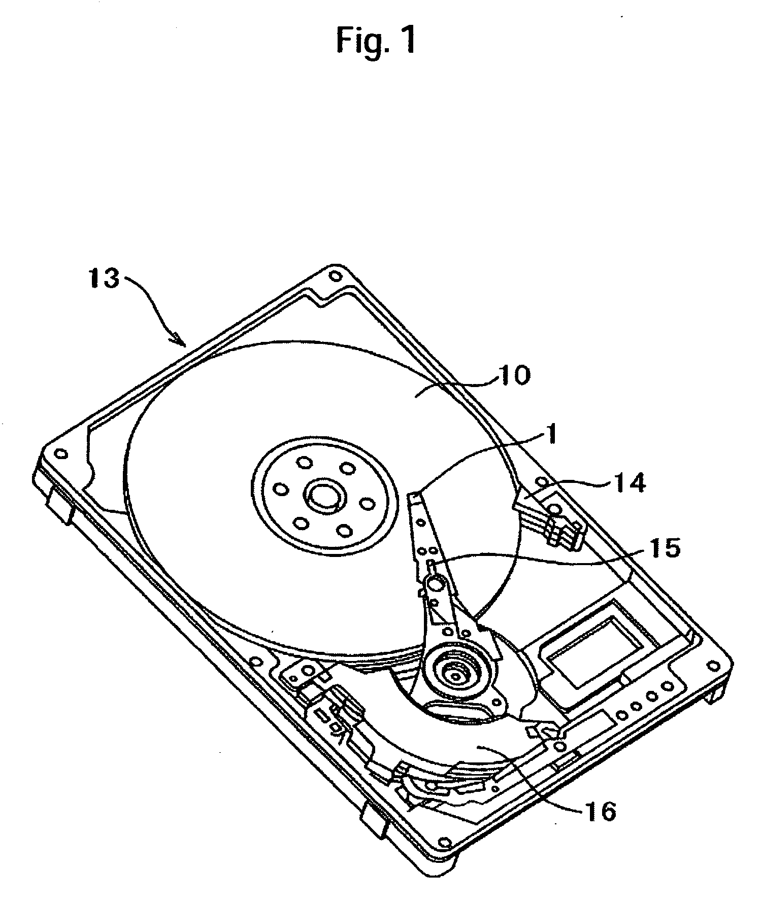
[0043] First, the whole configuration of a magnetic disk apparatus 13 according to the present embodiment is described with reference to FIG. 1. FIG. 1 is a perspective view of the magnetic disk apparatus 13 of the present embodiment. Note that a cover is omitted in FIG. 1.

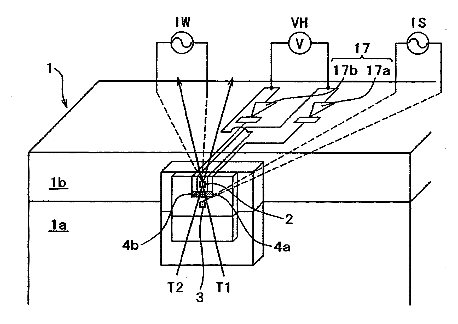
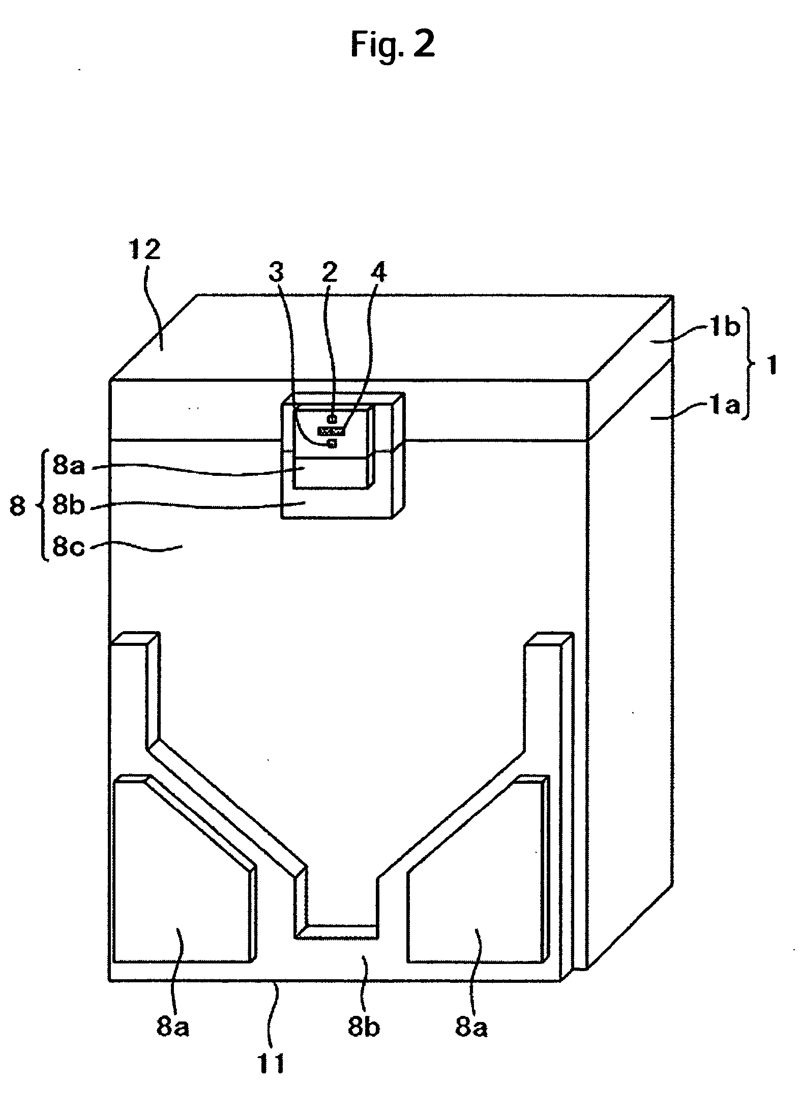
[0044] The magnetic disk apparatus 13 is constructed to have a disklike magnetic disk 10 on which magnetic information is stored and which is rotated by a spindle motor and a magnetic head slider 1 supported and placed in position radially by a load beam 15 on which a magnetic element 2 (see FIG. 2) and a playback element 3 (see FIG. 2) are carried. The magnetic head slider 1 runs over the magnetic disk 10 relative to it, and acts to read in information recorded on the magnetic disk 10 and to write information on the magnetic disk 10. The magnetic head slider 1 acts as a pneumat...

embodiment 2

[0067] Embodiment 2 of the present invention is next described using FIG. 7. FIG. 7 is a circuit diagram including connecting lead wires between a magnetic head slider 1 and a preamplifier 18 in a magnetic disk apparatus 13 of Embodiment 2 of the present invention. This Embodiment 2 is different from Embodiment 1 in the respects described next. In the other respects, Embodiment 2 is fundamentally identical with Embodiment 1.

[0068] In this Embodiment 2, a set of capacitor 21 and coil 22 is installed inside a magnetic head slider 1 instead of the thin film diode 17. That is, the capacitor 21 is connected in series with a heating element 4b. The coil 22 is connected in series with the heating element 4a. These series circuits are connected in parallel to form a series-parallel circuit. This series-parallel circuit is connected with an AC power supply IH for a preamplifier 18 via two lead wires from the magnetic head slider 1. In this Embodiment 2, heating elements 4a and 4b which shou...

embodiment 3

[0072] Embodiment 3 of the present invention is next described using FIGS. 8 and 9. FIG. 8 is a circuit diagram including connecting lead wires between the magnetic head slider 1 and the preamplifier 18 in the magnetic disk apparatus 13 of Embodiment 3 of the present invention. FIG. 9 is a perspective view of the magnetic head slider 1 in FIG. 8. This embodiment 3 differs from Embodiment 2 in the respects described next. In the other respects, this embodiment is fundamentally identical with Embodiment 2.

[0073] In this Embodiment 3, series circuits of capacitors 21a-21c and coils 22a-22c are connected in series with the heating elements 4a-4c. These series circuits are connected in parallel to form a series-parallel circuit. This series-parallel circuit is connected with a power supply IH for a preamplifier 18 via two lead wires from the magnetic head slider 1. In this Embodiment 3, the heating elements 4a-4c that should do heating are switched by varying the frequency of the AC pow...


PUM

PropertyMeasurementUnit
thicknessaaaaaaaaaa
thicknessaaaaaaaaaa
lengthaaaaaaaaaa

Abstract

In a magnetic disk apparatus, mounting of plural heating elements to a magnetic head slider is permitted. Thermally assisted magnetic recording from inner to outer surface is permitted at a small amount of power consumption. In one embodiment, the magnetic disk apparatus has a magnetic disk on which magnetic information is recorded, a magnetic head slider having an air bearing surface for floating from the magnetic disk in proximity thereto, and a rotary actuator moving over the disk arcuately while supporting the magnetic head slider by a suspension. A recording element acting to record magnetic information on the magnetic disk, a playback element acting to play back the magnetic information recorded on the magnetic disk, and plural heating elements acting to locally heat the magnetic disk are carried on the magnetic head slider. A circuit for switching energization to the plural heating elements and according to information about the direction of a DC power supply VH, frequency contained in an AC power supply, or the like is formed.

Description

CROSS-REFERENCES TO RELATED APPLICATIONS [0001] This application claims priority from Japanese Patent Application No. JP2004-355107, filed Dec. 8, 2004, the entire disclosure of which is incorporated herein by reference. BACKGROUND OF THE INVENTION [0002] The present invention relates to a magnetic disk apparatus fitted with a magnetic head slider and is especially adapted for a magnetic disk apparatus fitted with a magnetic head slider of the thermally assisted type which locally reduces the coercive force of a magnetic disk by a heating element and makes a magnetic recording at this location using a recording element. [0003] To realize a magnetic disk apparatus of high recording density, it is necessary to make small recording particles on a magnetic disk. And, to permit small magnetization patterns to exist stably, it is necessary to enhance the coercive force of the magnetic disk. However, it has become more difficult to rewrite small recording particles of high coercive force w...

Claims


Application Information

Patent Timeline
Patent Type & Authority Applications(United States)
IPC IPC(8): G11B17/00
CPCG11B5/012G11B5/127G11B5/3103G11B5/3967G11B5/4886G11B5/4923G11B5/4969G11B2005/0005G11B2005/0021
Inventor KURITA, MASAYUKIHAMAGUCHI, TAKEHIKOKOHIRA, HIDEKAZUTOKUYAMA, MIKIO
Owner WESTERN DIGITAL TECH INC
Why Eureka
Try Eureka