Heat dissipating apparatus

a technology of heat dissipation apparatus and heat dissipation chamber, which is applied in the direction of cooling/ventilation/heating modification, semiconductor/solid-state device details, semiconductor devices, etc., can solve the problems of failure of heat dissipation of electronic components, and unaddressed needs in the industry. achieve the effect of dissipating heat of electronic components and strong airflow

Inactive Publication Date: 2006-06-08
HON HAI PRECISION IND CO LTD +1
View PDF27 Cites 9 Cited by
  • Summary
  • Abstract
  • Description
  • Claims
  • Application Information

AI Technical Summary

Benefits of technology

[0007] The present invention provides a heat dissipating apparatus for dissipating heat of an electronic component. According to one embodiment, the heat dissipating apparatus includes a heat sink having a base plate for contacting the electronic component. A number of main fins extend from the base plate. A cooling fan is mounted on the heat sink. A center of the cooling fan offsets in a first direction from a center of the electronic component, so that a portion of the cooling fan that generates more and stronger airflows than the center of the cooling fan does is aligned with the center of the electronic component.

Problems solved by technology

For a cooling fan, unfortunately, its center portion generates little and weak airflow during operation.
Therefore, in the above-described configuration of the heat dissipating apparatus, the cooling fan 6 is generally unable to draw adequate air through the center portion of the heat dissipating apparatus to dissipate the significant amount of heat accumulated thereon.
This may cause a failure of heat dissipating of the electronic component 2.
Therefore, a heretofore-unaddressed need exists in the industry to address the aforementioned deficiencies and inadequacies.

Method used


Image

  • Heat dissipating apparatus
  • Heat dissipating apparatus

Examples


Embodiment Construction

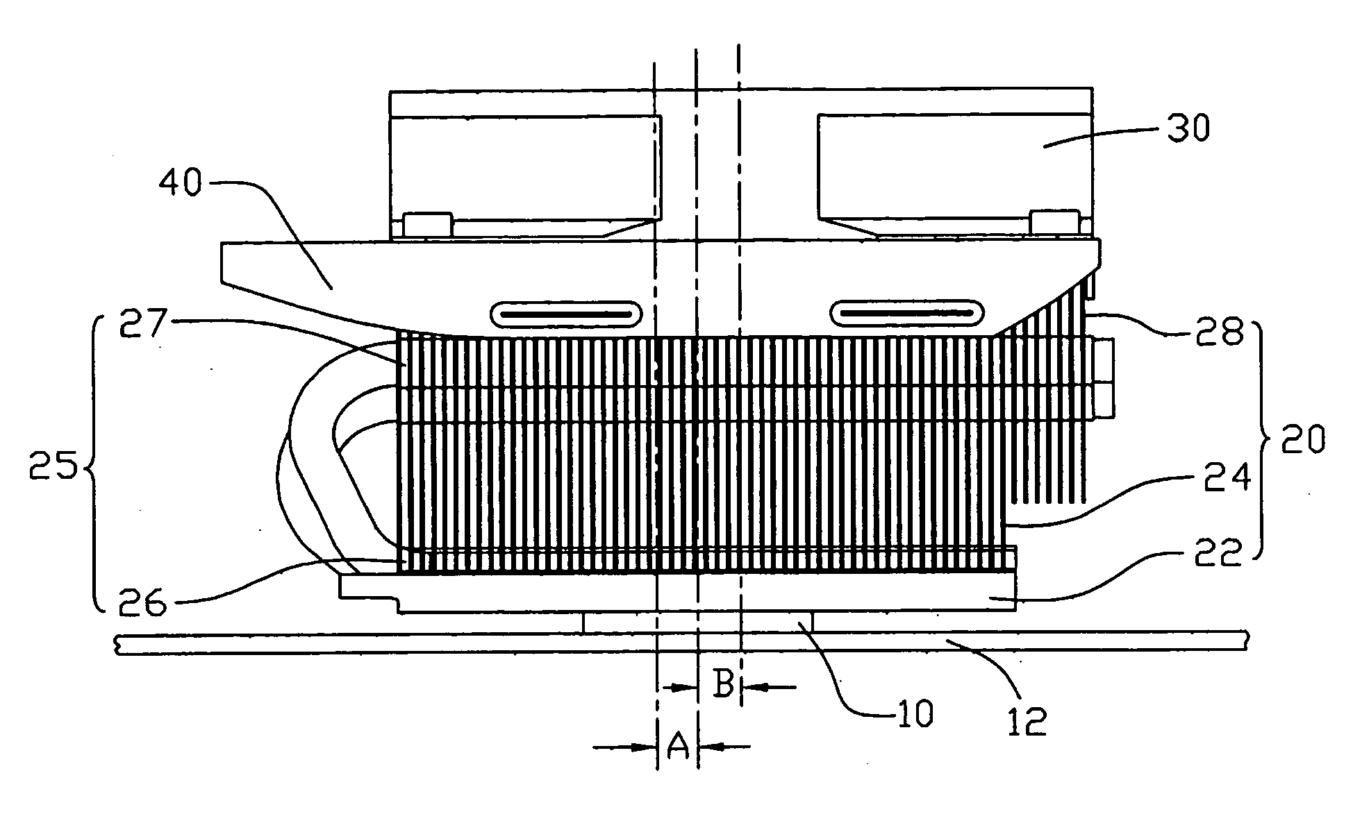
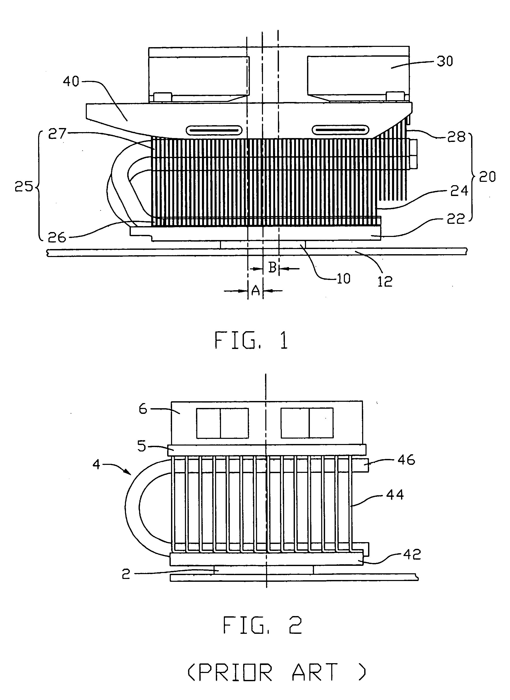
[0011]FIG. 1 illustrates by way of example a heat dissipating apparatus in accordance with a preferred embodiment of the present invention, together with an electronic component 10 mounted on a printed circuit board 12. The heat dissipating apparatus comprises a heat sink 20 attached on the electronic component 10, two heat pipes 25 extending in the heat sink 20, and a cooling fan 30 mounted on the heat sink 20.

[0012] The heat sink 20 comprises a base plate 22, a plurality of parallel main fins 24 and a plurality of parallel additional fins 28. The base plate 22 comprises a first surface contacting the electronic component 10 to absorb heat therefrom. The main fins 24 extend upwardly from an opposite second surface of the base plate 22. In the preferred embodiment, the additional fins 28 are separated from the base plate 22.

[0013] Each heat pipe 25 has a U-shaped structure, one end of which serves as an evaporating section 26, and the other which serves as a condensing section 27....


PUM


Abstract

A heat dissipating apparatus includes a heat sink (20) having a base plate (22) for contacting an electronic component (10). A number of main fins (24) extend from the base plate. A cooling fan (30) is mounted on the heat sink. A center of the cooling fan offsets in a first direction from a center of the electronic component, so that a portion of the cooling fan that generates more and stronger airflows than the center of the cooling fan does is aligned with the center of the electronic component.

Description

BACKGROUND OF THE INVENTION [0001] 1. Field of the Invention [0002] The present invention relates generally to an apparatus for dissipating heat, and more particularly to a heat dissipating apparatus having a heat sink and a fan for providing forced airflows directed to the heat sink to dissipate heat generated by an electronic component. [0003] 2. Description of Related Arts [0004] As ICs (Integrated Circuits) such as computer CPUs (Central Processing Units) are being designed to run faster and faster, more and more heat are being generated by these ICs. Heat dissipating apparatus are typically used to dissipate the heat generated by these ICs. [0005]FIG. 2 illustrates a conventional heat dissipating apparatus for cooling an electronic component 2. The heat dissipating apparatus generally includes a heat sink 4 rested on the electronic component 2, a retaining bracket 5 and a cooling fan 6 positioned to the heat sink 4 by the retaining bracket 5. The heat sink 4 includes a base pla...

Claims


Application Information

Patent Timeline
Patent Type & Authority Applications(United States)
IPC IPC(8): H05K7/20
CPCH01L23/427H01L23/467H01L2924/0002H01L2924/00
Inventor YU, FANG-XIANGLEE, MENG-TZULIN, SHU-HOLUO, JUN
Owner HON HAI PRECISION IND CO LTD
Why Eureka
Try Eureka