Stirring and mixing device

a mixing device and mixing technology, applied in the direction of mixing, rotary stirring mixer, transportation and packaging, etc., can solve the problems of difficult to mix powder and secondary aggregates, difficult to disperse formed secondary aggregates into liquid, and difficulty in later introduction of powder, etc., to achieve the effect of adjusting the viscosity and improving the stirring efficiency

Inactive Publication Date: 2006-06-08
REICA KOGYO kk
View PDF41 Cites 100 Cited by
  • Summary
  • Abstract
  • Description
  • Claims
  • Application Information

AI Technical Summary

Benefits of technology

[0025] The disposition of the partition plate causes a turbulent flow in the passage of the casing to further improve the stirring efficiency.
[0026] The disposition of the filter makes it possible to obtain a desired dissolved material, mixture, reactant or the like b

Problems solved by technology

For example, it is known that where liquid is added to mix with powder, powder is added to mix with liquid, or powder and liquid are simultaneously added to mix them, secondary aggregated particles (so-called undissolved lumps) of the powder are produced in the liquid, and it is quite difficult to disperse the formed secondary aggregates into the liquid again.
In addition, the secondary aggregates block a raw material introduction port, resulting in readily causing a phenomenon that later introduction of powder becomes difficult.
However, none of the above-described mixing devices and mixing methods can prevent the powder introduction port from being blocked by compl

Method used


Image

  • Stirring and mixing device
  • Stirring and mixing device
  • Stirring and mixing device

Examples


Embodiment Construction

[0039] Preferred embodiments of the present invention will now be described with reference to the drawings.

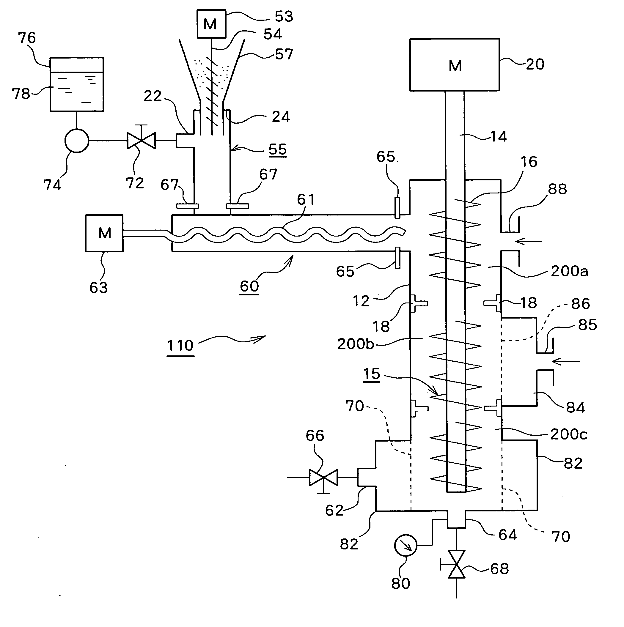
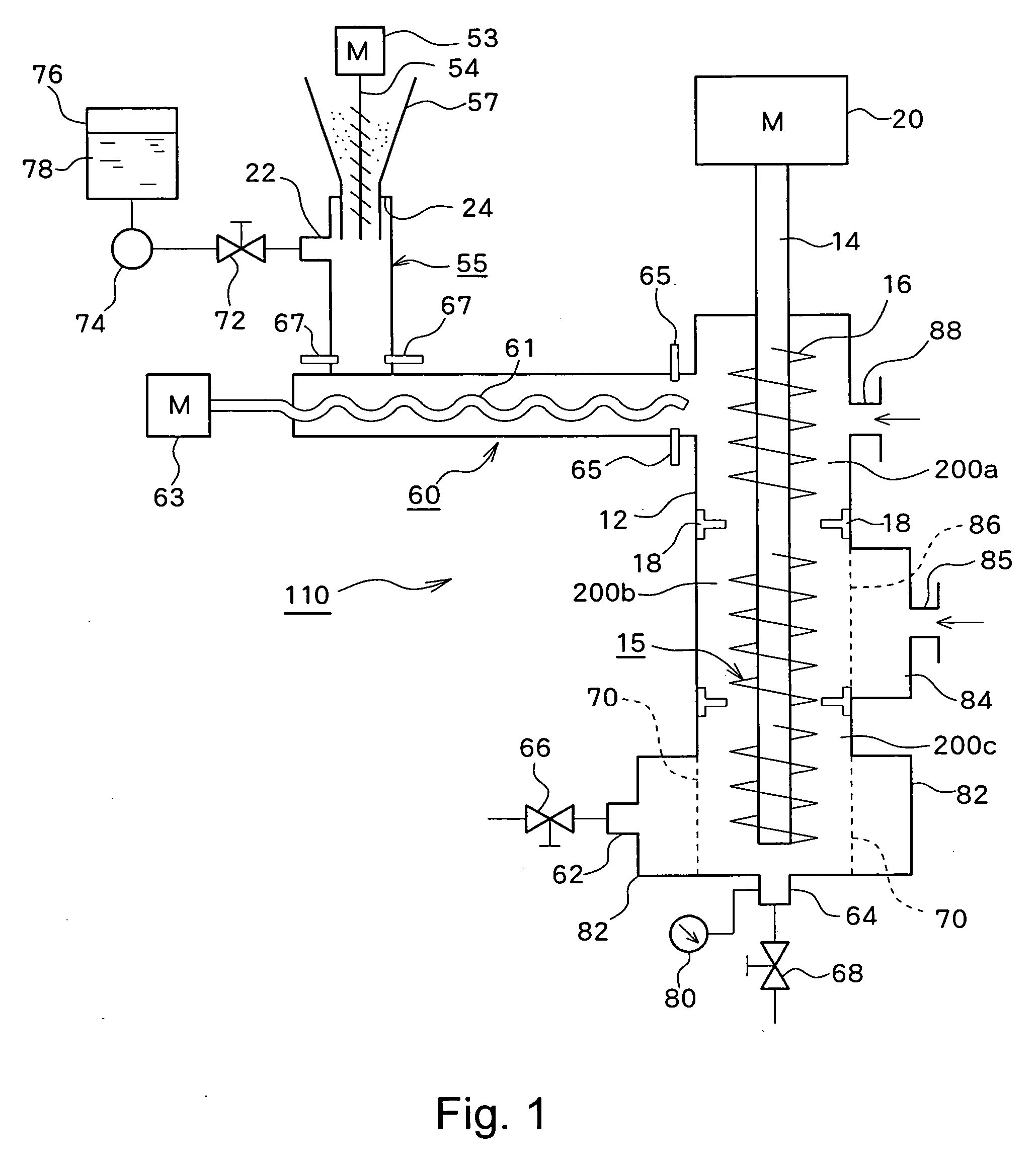
[0040] One example of the stirring and mixing device of the present invention will be described for its structure with reference to FIG. 1.

[0041] A stirring and mixing device 110 has an introduction pipe 55 which is provided with a powder introduction port 24 and a liquid introduction port 22, an extrusion pipe 60 which is connected to the introduction pipe 55 and extrudes a mixture of powder and liquid introduced through the introduction pipe 55 to its one end portion, a casing 12 which is connected to one end portion of the extrusion pipe 60 and provided with a passage through which a fluid of the extruded mixture is made to flow, and a stirrer 15 which is disposed within the casing 12 and comprised of a shaft portion 14 connected to a drive source 20 and a stirring blade 16 attached to the external surface of the shaft portion 14. A funnel-shaped powder introducing device ...


PUM

PropertyMeasurementUnit
Pressureaaaaaaaaaa
Viscosityaaaaaaaaaa
Sizeaaaaaaaaaa

Abstract

A stirring and mixing device 110 comprises an introduction pipe 55 which is provided with a powder introduction port 24 and a liquid introduction port 22, an extrusion pipe 60 which is connected to the introduction pipe 55 and extrudes a mixture of powder and liquid introduced through the introduction pipe 55 to its one end portion, a casing 12 which is connected to one end portion of the extrusion pipe 60 and provided with a passage through which a fluid of the extruded mixture is made to flow, and a stirrer 15 which is disposed within the casing 12 and comprised of a shaft portion 14 connected to a drive source 20 and a stirring blade 16 attached to the external surface of the shaft portion 14. A funnel-shaped powder introducing device 57 is attached to the powder introduction port 24, a feeder 54 for conveying powder is disposed in the powder introducing device 57, and the feeder 54 is connected to an oscillatory rotation drive source 53.

Description

[0001] The entire disclosures of Japanese Patent Application Nos. 2004-354736 and 2005-219673, including specification, claims, drawings and abstract are incorporated herein by reference in their entirety. BACKGROUND OF THE INVENTION [0002] 1. Field of the Invention [0003] The present invention relates to a stirring and mixing device which introduces powder by rotating a feeder in an oscillatory manner for conveying the powder, and stirs and mixes with liquid. [0004] 2. Description of the Related Art [0005] For example, it is known that where liquid is added to mix with powder, powder is added to mix with liquid, or powder and liquid are simultaneously added to mix them, secondary aggregated particles (so-called undissolved lumps) of the powder are produced in the liquid, and it is quite difficult to disperse the formed secondary aggregates into the liquid again. In addition, the secondary aggregates block a raw material introduction port, resulting in readily causing a phenomenon t...

Claims


Application Information

Patent Timeline
IPC IPC(8): B01F11/00B01F15/02
CPCB01F3/1221B01F5/0471B01F15/0202B01F15/0251B01F2003/0028B29B7/423B29B7/603B29B7/428B29B7/429B29B7/72B29B7/7485B29C48/385B01F23/023B01F23/53B01F25/314B01F35/711B01F35/71775
Inventor TANIGUCHI, TORUFUJIOKA, NOBUAKI
Owner REICA KOGYO kk
Why Eureka
Try Eureka