Demodulation and phase estimation of two-dimensional patterns

a two-dimensional pattern and phase estimation technology, applied in the field of two-dimensional code patterns, can solve problems such as defects and errors that may also be produced by the preliminary demodulation process, phase estimation errors, and restrictions on the smoothness of curves

Inactive Publication Date: 2006-06-08
CANON KK
View PDF11 Cites 49 Cited by
  • Summary
  • Abstract
  • Description
  • Claims
  • Application Information

AI Technical Summary

Problems solved by technology

However, conventional methods of demodulating closed curve fringe patterns, including circular and elliptical fringe patterns, inevitably produce ambiguities.
These additional constraints may include restrictions on the smoothness of curves within the fringe patterns.
In addition to ambiguities other defects and errors may also be produced by the preliminary demodulation process.
The artefacts result in errors in phase estimation, and specifically in regions where an angle of the fringe pattern is close to perpendicular with the half-plane discontinuity line.
However, the frequency components derived from circular or elliptical fringe patterns are also “circular” and no discontinuity line could be defined which does not cut through the frequency signal.
Other methods based on local (small kernel) demodulation may avoid the errors of the FTM, but typically fail to disambiguate correctly when there are strong perturbations in the underlying fringe pattern.
A serious deficiency with such gradient-based methods is that at the ridges and valleys of images, the gradient has zero magnitude.
Gradient methods are therefore unable to provide information about pattern direction in such regions.
Methods based on the statistical properties of spatial phase histograms have been proposed, but are heavily dependent on certain restrictive, and often unrealistic criteria.
More recently methods based upon the correlation between patterns have been proposed but are very sensitive to the number of full fringes in the frames.
Accordingly, current methods of demodulating sequences of phase-related fringe-patterns are unsatisfactory in many situations, especially for a small number of phase-related fringe-patterns, and many algorithms do not work in the case of three or four frames.

Method used


Image

  • Demodulation and phase estimation of two-dimensional patterns
  • Demodulation and phase estimation of two-dimensional patterns
  • Demodulation and phase estimation of two-dimensional patterns

Examples


Embodiment Construction

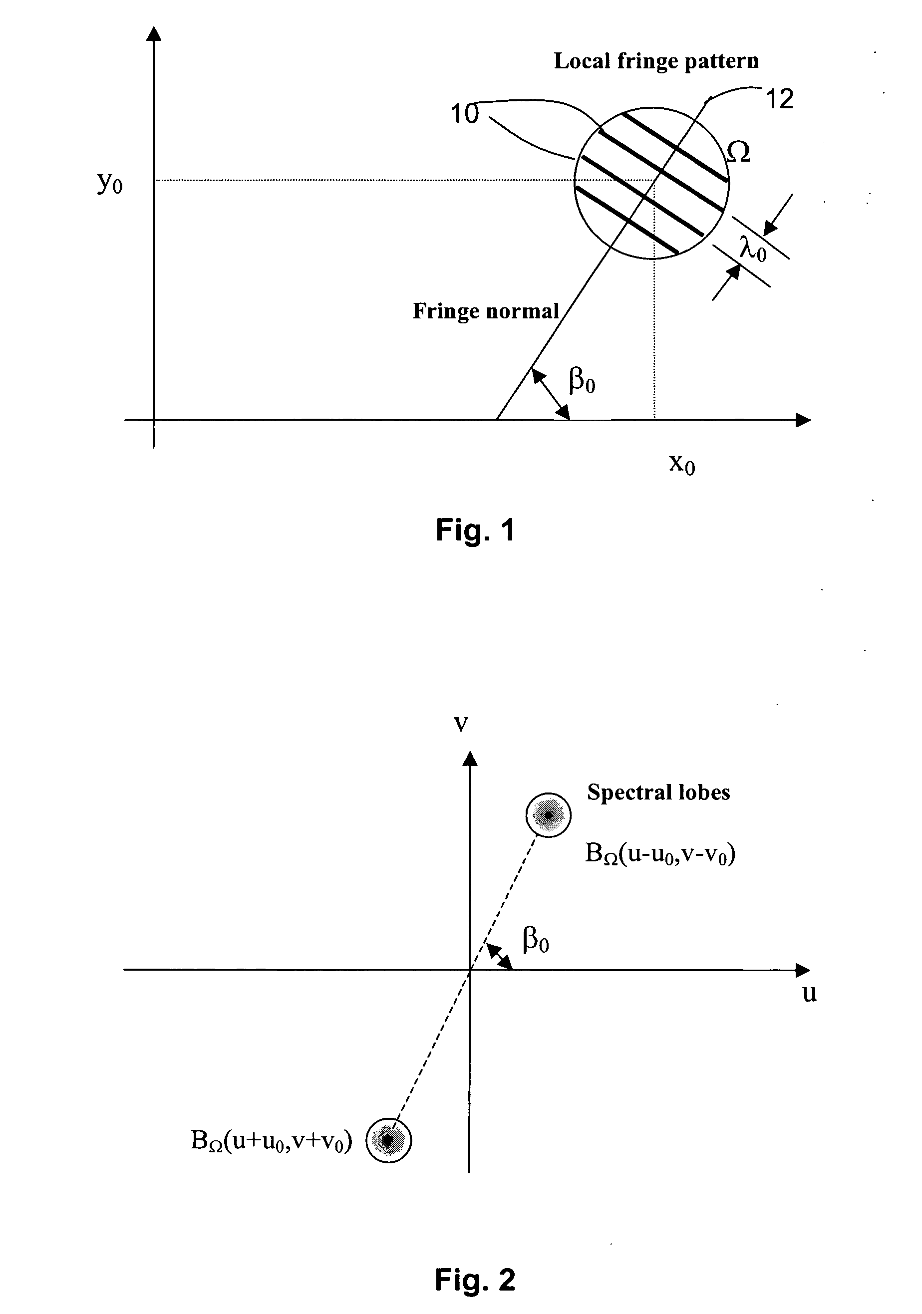
[0077] Consider a two-dimensional fringe pattern with intensity of the fringe pattern as follows:

f(x,y)=a(x,y)+b(x,y).cos[2π(u0{x−xo}+v0{y−y0})+χ]  (1)

[0078] Position coordinates (x, y) may be continuous for an analog pattern or discrete for digital patterns. A background level is denoted by a(x,y) while an amplitude modulation term is denoted by b(x,y), both assumed to be slowly varying functions. Phase term χ(x0,y0) presents the local offset of the overall phase term in the square brackets [ ] of Equation (1).

[0079] Referring to FIG. 1 where a 2-dimensional fringe pattern or AM-FM pattern, located around a point (x0,y0) and formed by a number of fringes 10 is shown. A small region of interest is defined by Ω. Within this small region Ω, the spatial frequency components u0 and v0 are slowly varying so that they are effectively constant around the point (x0,y0), making the carrier a linear function of x and y. A normal 12 to the local fringes 10 is at an angle β0 to the x-axis.

[00...


PUM


Abstract

A method (100) of demodulating a real two-dimensional pattern (110) is disclosed. The method (100) estimates (120, 130) a quadrature two-dimensional pattern from the real two-dimensional pattern (110) using a smooth phase only transform having an anti-symmetric phase, such as a spiral phase filter (140). A demodulated image is created by combining (180) the real two-dimensional pattern (110) and the estimated quadrature two-dimensional pattern.

Description

FIELD OF THE INVENTION [0001] The present invention relates to two-dimensional code patterns and more particularly to the automatic demodulation of fringe patterns. The present invention also relates to the automatic estimation of pattern and texture orientation of an image. The present invention further relates to phase demodulation of a sequence of fringe patterns with arbitrary and unknown phase shifts between them. Such patterns typically occur in optical interferograms, but can also occur in interferograms produced by more general waves such as acoustic, synthetic aperture radar (SAR), ultrasound, and x-ray. More general image sequences, such as video, can in some cases also be modelled as fringe pattern sequences. BACKGROUND [0002] Methods exist for demodulating fringe patterns. Examples of such patterns are illustrated in FIGS. 5 and 14A. However, conventional methods of demodulating closed curve fringe patterns, including circular and elliptical fringe patterns, inevitably p...

Claims


Application Information

Patent Timeline
Patent Type & Authority Applications(United States)
IPC IPC(8): G06K9/64G06K9/36G06K9/00G01B9/02G06T3/00G06T5/00G06T5/10G06T5/20G06T7/40
CPCG06K9/00067G06T2207/20056G06T7/70G06V40/1347
Inventor LARKIN, KIERAN GERARDOLDFIELD, MICHAEL ALEXANDERBONE, DONALD JAMES
Owner CANON KK
Why Eureka
Try Eureka