
Dental splints and apparatus and method for making dental splints

a dental splint and apparatus technology, applied in the field of dental devices, can solve the problems of large error room, only restraining invasive measures, and relieving the severity of the patient's condition, so as to relieve pain and discomfort for patients, and the effect of reducing pain

Inactive Publication Date: 2006-06-08
DYLINA TIM J
View PDF16 Cites 11 Cited by
  • Summary
  • Abstract
  • Description
  • Claims
  • Application Information

AI Technical Summary

Benefits of technology

[0009] The maxillary splint is then inserted into the patient's mouth. Dental acrylic is placed in the U-shaped trough of the mandibular stent, which is then inverted and placed over the mandibular teeth in alignment with the maxillary splint. The acrylic in the mandibular stent is allowed to cure to form the mandibular splint. The mandibular splint is then removed, and any rough surfaces are smoothed. The teeth cavities in the splints cause the patient to maintain the maxilla and the mandible in proper alignment, keeping maximum registry and alignment of the maxillary and mandibular teeth, thereby alleviating the pain associated with TMD, and relieving the patient from pain and discomfort associated with clenching, bruxism, and resulting headaches.

Problems solved by technology

Invasive measures are usually only resorted to when more conservative measures prove ineffective in relieving the severity of the patient's condition.
The room for error is vast.
If the doctor does not have experience in manipulating the patient in centric relation, errors in splint fabrication can occur.
Also, new, inexperienced dentists find it difficult to use and balance face-bows, often resulting in such inexperienced dentists opting out of treating TMD because of the difficulty in correcting alignment and finding balance in the temporomandibular joints.

Method used


Image

  • Dental splints and apparatus and method for making dental splints
  • Dental splints and apparatus and method for making dental splints
  • Dental splints and apparatus and method for making dental splints

Examples


Embodiment Construction

[0022] The present invention is a pair of dental splints for treating temperomandibular joint disorder and similar conditions involving the relation of the maxilla and mandible, together with an apparatus and method for making dental splints that permits fabricating the splints in the dental practitioner's office instead of a dental laboratory. The structure of the splints will become clear by explaining the apparatus and method of making the splints.

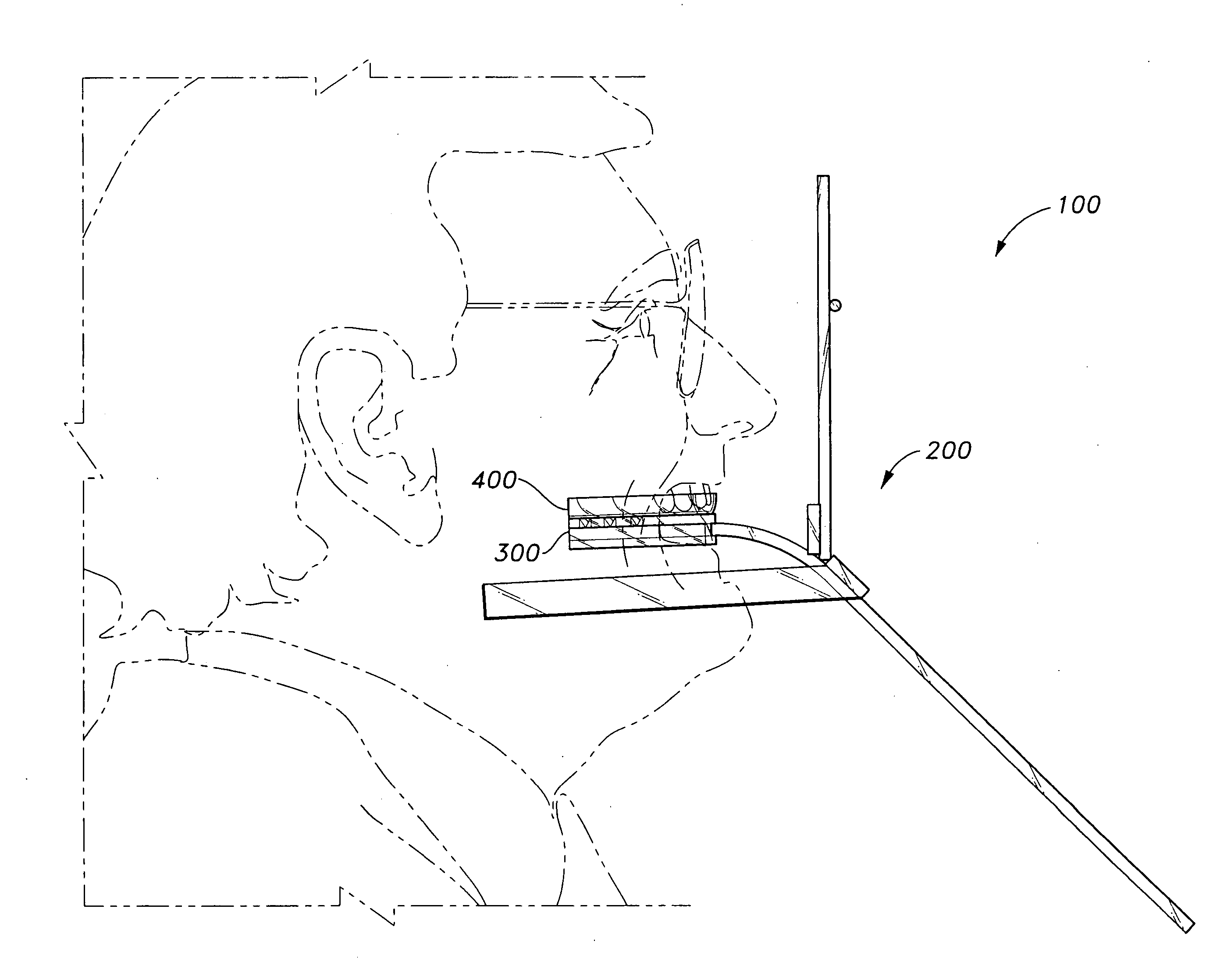
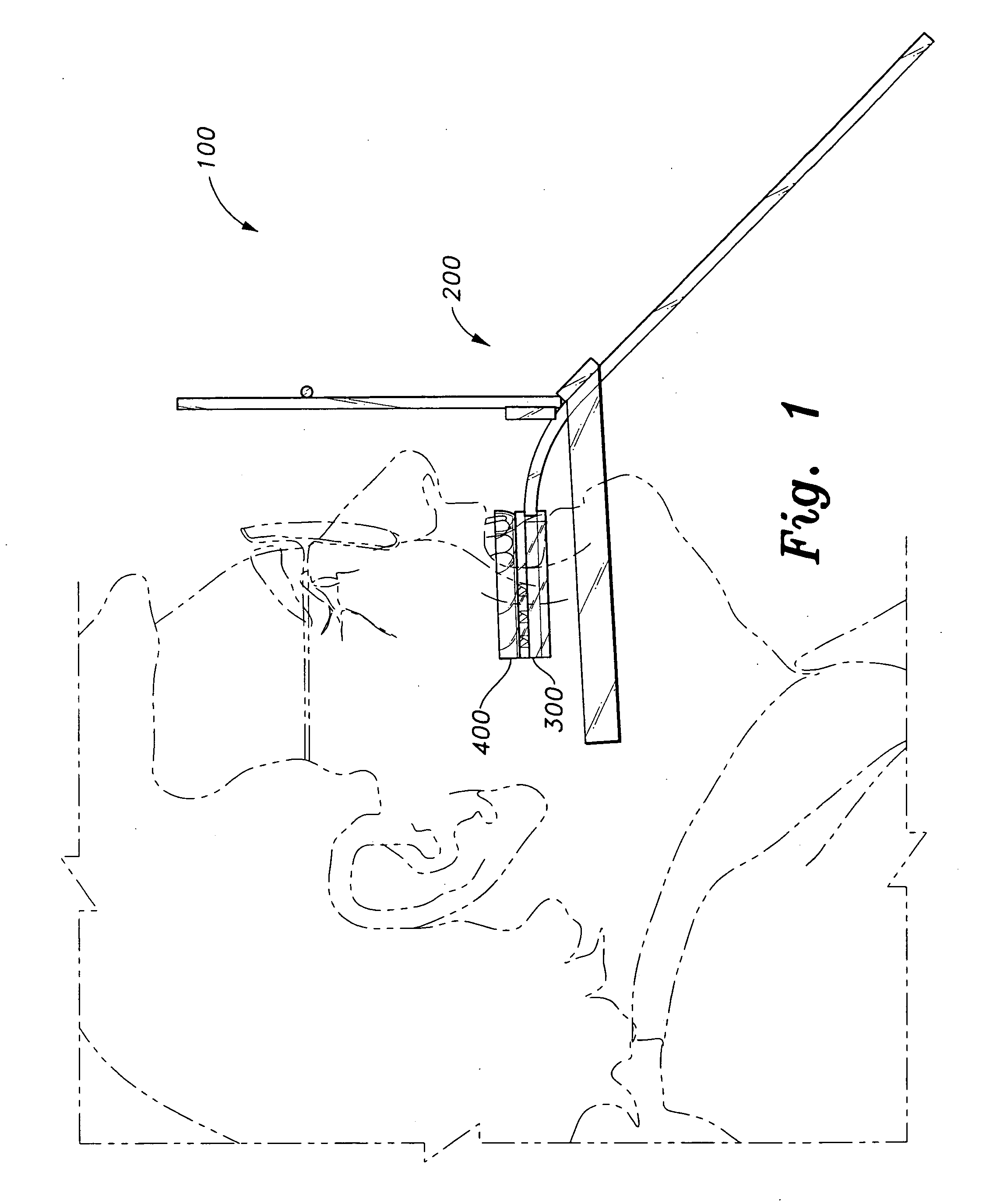
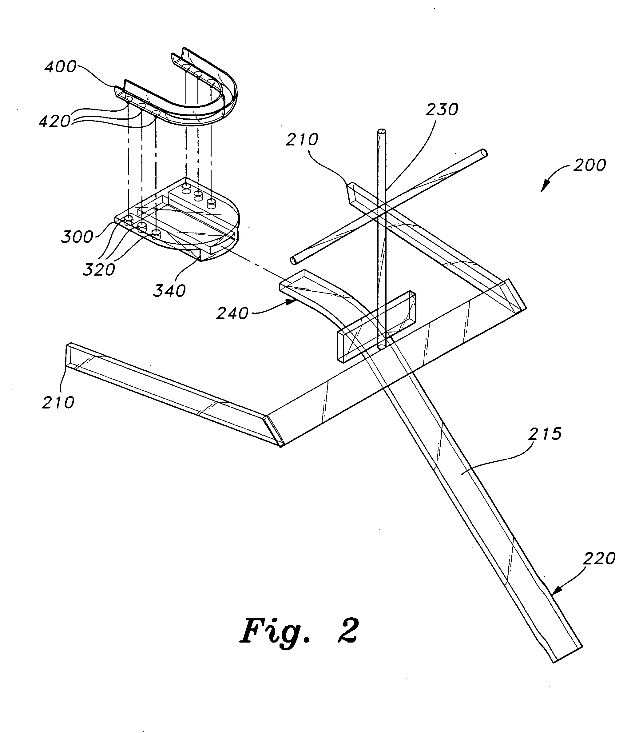
[0023] Referring to FIGS. 1, 2 and 3, the apparatus is designated generally as 100 in the drawings. The apparatus 100 includes a maxillary plane analyzer 200, a holding plate 300 and a maxillary stent 400. The holding plate 300 removably holds the stent 400. The dentist uses the analyzer 200 to determine the patient's occlusal plane and orient the stent 400 in the proper angle on the patient's maxilla.

[0024] The analyzer 200 is a support and manipulating body having a handle or lever 215, a cruciform upright 230, and a U-shaped base h...


PUM


Abstract

The dental splints are used for treating temporomandibular disorders, clenchers, bruxism and headaches resulting from improper alignment of the jaws. The dental splints include a maxillary splint and a mandibular splint. Both splints are formed from stents having a U-shaped trough filled with a dental acrylic and cured in situ on the patient's maxillary teeth and mandibular teeth, respectively. The apparatus includes a maxillary plane analyzer and a holding plate. The holding plate is a U-shaped plate having a central slot for receiving a stem of the plane analyzer and a plurality of recesses for receiving temporary cleats extending from the maxillary stent. The plane analyzer includes a handle, a U-shaped base mounted on the handle and including a pair of arms adapted for extending to either side of the mandible, a stem extending between the arms of the base, and a cruciform upright mounted on the handle.

Description

BACKGROUND OF THE INVENTION [0001] 1. Field of the Invention [0002] The present invention relates to dental devices, and more particularly to an orthotic dental splint, and to an apparatus and method of making the splints to treat temporomandibular disorders, clenchers, bruxism and headaches that can be used by the dentist to make the splints in the dentist's office instead of a dental laboratory. [0003] 2. Description of the Related Art [0004] Dental ailments encompass a variety of disorders that require treatment ranging from simple methods to invasive surgery. Temporomandibular disorder (TMD) is one such dental problem. Proper functioning of the lower jaw is dependent, in part, upon temporomandibular joints and associated muscles. The temporomandibular joints are disposed on each side of the jaw and connect the lower jaw to the temporal bones of the skull. The temporomandibular joints (TMJs) are the most used joints in the body; among other functions, the TMJs are used to speak, ...

Claims


Application Information

Patent Timeline
IPC IPC(8): A61C3/00A61C1/00A61C5/14
CPCA61C7/08A61F2005/563
Inventor DYLINA, TIM J.
Owner DYLINA TIM J
Learn More