Micro aerial vehicle

a technology of micro-aerial vehicles and rotors, which is applied in the field of micro-aerial vehicles with rotors, can solve problems such as counterbalancing reaction torque, and achieve the effect of counterbalancing reaction torque and less expansion

Inactive Publication Date: 2006-06-08
AIRROBOT
View PDF1 Cites 25 Cited by
  • Summary
  • Abstract
  • Description
  • Claims
  • Application Information

AI Technical Summary

Benefits of technology

[0011] To solve above problems, this invention is intended to offer a system which counterbalances the reaction torque that is simple, less expansive, and light on single rotor micro-sized aerial vehicle which can perform VTOL.

Problems solved by technology

Also, each blades are place to be tilted in certain angle so the air flow to act on the blades to spin on opposite direction of the rotor, which then counterbalance the reaction torque.

Method used


Image

  • Micro aerial vehicle
  • Micro aerial vehicle
  • Micro aerial vehicle

Examples


Embodiment Construction

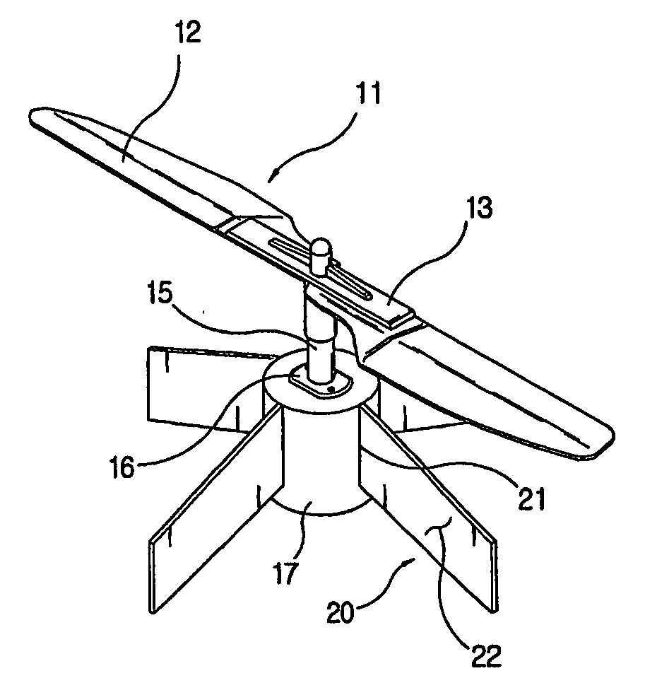
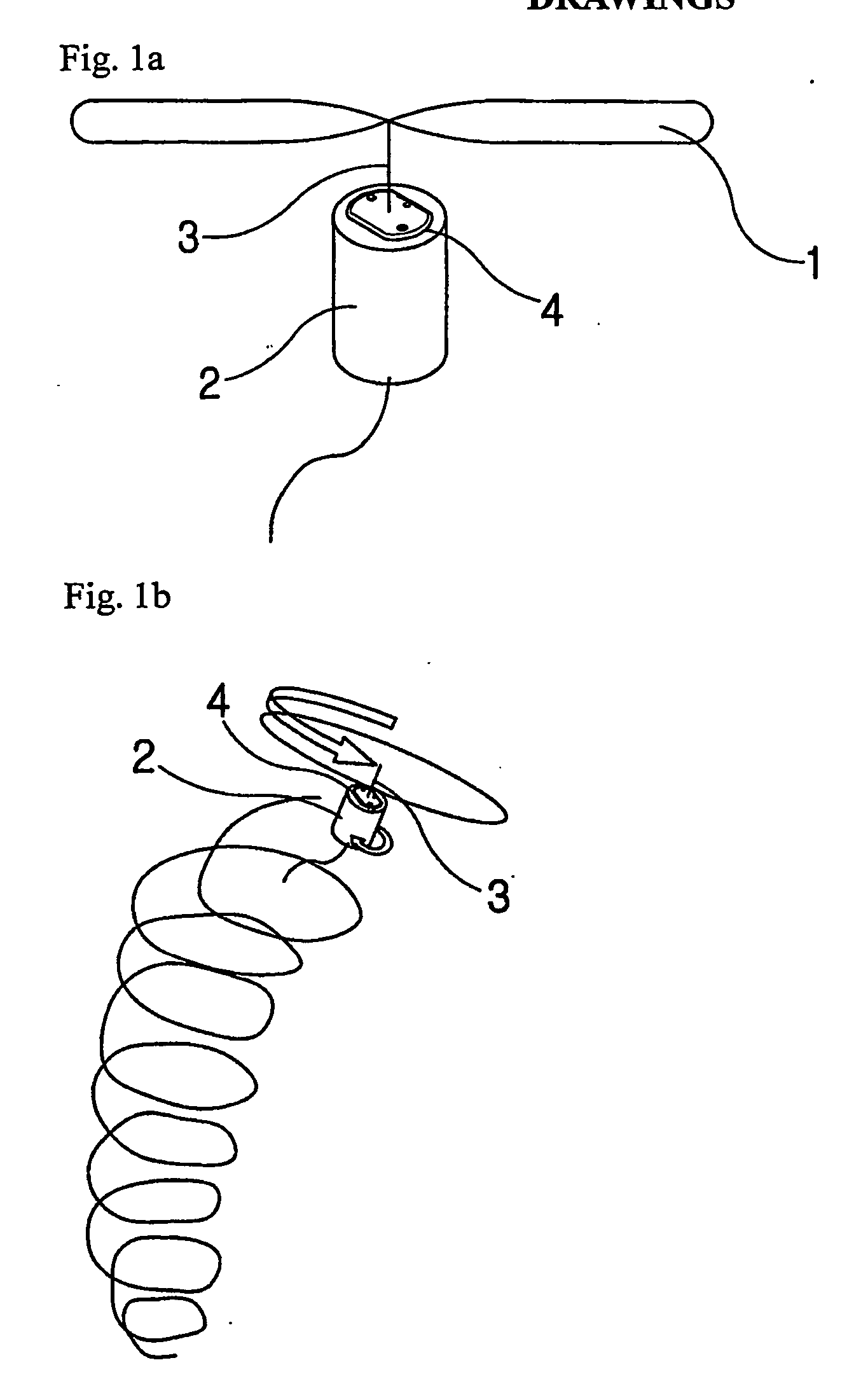
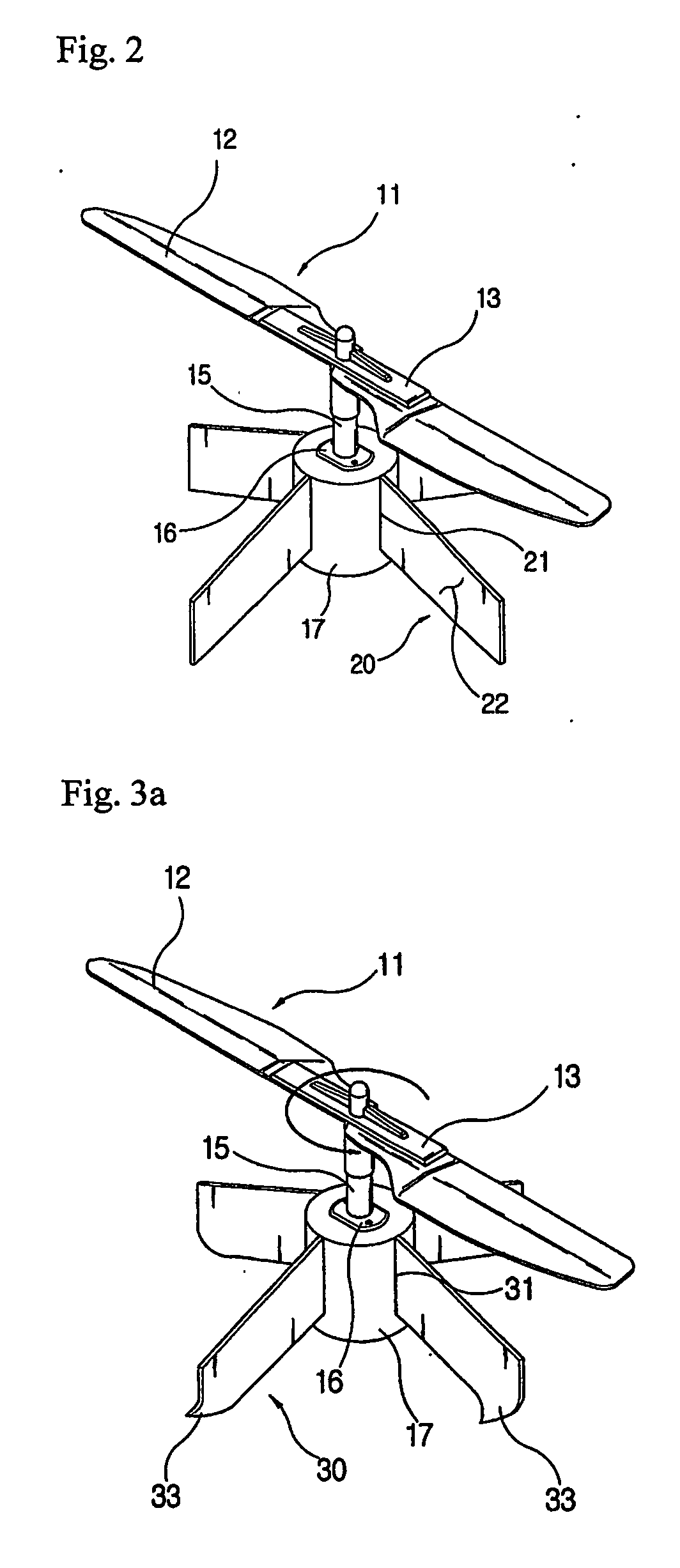
[0038] From the below, we will take a look at preferred embodiment of our invention through the figures that are attached. These are only suggestive examples, not the exact outline which would limit the use of the invention. [0039]FIG. 2 is the three dimensional draft on the prototype of the micro aerial vehicle. As you see on the draft, pair of blades (12) shaped in airfoil is attached from hub (13) to the drive axle (15), and this drive axle is designed to spin as the rotor drive turns (16), which then will make the attached blades to spin. It is suggested that a motor to be used for rotor drive. [0040] It is unnecessary to describe the structure of blades, because they are designed in a traditional air foil form. It is shown in FIG. 2 that only a pair of blade is used, but number of blades could be varied. (3, 4, 5 and so on) [0041] As the rotor (11) turns, several blades in air foil shape also turns, and air above the blade would be sucked through the blades causing the body (17...


PUM


Abstract

The purpose of this invention is to provide an ultra-miniature aircraft which is able to perform ‘Vertical Take-off and Landing (VTOL)’ and maintaining altitude when the vehicle is moving or when the horizontal velocity of a vehicle is at 0 by getting life only from a single rotor's rotation, and without using separate stabilizers such as a tail-rotor or a gyro. To fulfill the above purpose, this invention comprises: several blades in airfoil shape that are places in calculated angle and space; hubs that connect the blade to with a body of a vehicle; a rotor which gives lifting force with its spin; a spin-able axle which its vertical hem is bound to the hubs; a rotor drive that is needed to spin the rotor; a vehicle body that is placed right under the rotor in order to fly from the lift that is obtained by revolutions of the rotor; fixed-wings that are placed in certain angle and space around the outside of the vehicle body in order to reduce a reaction torque, which affects the body to turn the opposite direction of the rotor, from the rotor's movement; and a reaction-torque-counter-balancing-system on each of the above fixed-wings that offsets the reaction torque aggressively.

Description

TECHNICAL FIELD [0001] This invention is about the micro-size vehicle with rotor. In detail, the invention is able to perform ‘Vertical Take-Off and Landing (VTOL)’ by getting lift only from a single rotor's rotation, and maintaining altitude when the vehicle is moving or when the horizontal velocity of a vehicle is at 0 without using separate stabilizers such as tail rotors or gyros. [0002] Specially, development of inventions such as ours could be used in RC (Radio Control System) airplanes in less expensive ways. Moreover, the invention could be used for a small helicopter which gathers information on areas where there was a disaster, or areas where geographic exploration is needed. Also, it could be used for many military purposes. BACKGROUND ART [0003] Airplanes are generally divided in two categories; fixed-wing and rotary-wing. Fixed-wing aircrafts get life from either propellers or engine's thrust; there are the ones that we generally call the ‘airplane.’ Rotary-wing aircraf...

Claims


Application Information

Patent Timeline
Patent Type & Authority Applications(United States)
IPC IPC(8): A63H27/127B64C27/06B64C39/02
CPCA63H27/12B64C39/024B64C39/028B64C2201/027B64C2201/042B64C2201/104B64C2201/108B64C2201/146B64C2201/165B64U30/10B64U10/13B64U30/20B64U50/19B64U50/13B64U2201/20A01K61/51A01K61/73
Inventor LEE, CHANG YEALSONG, NAM KWON
Owner AIRROBOT
Why Eureka
Try Eureka