Directly laminated plate

Inactive Publication Date: 2013-05-23
SURFACE TECH
View PDF4 Cites 2 Cited by
  • Summary
  • Abstract
  • Description
  • Claims
  • Application Information

AI Technical Summary

Benefits of technology

[0031]The solution according to the invention for avoiding paper expansion makes it possible to manufacture boards displaying a structured surface by a continuous pressing method, where the structure corresponds exactly to the graphic representation of an underlying decorative layer. In this context, the

Problems solved by technology

As a result, there is no danger of the dry core absorbing so much resin th

Method used


Image

  • Directly laminated plate
  • Directly laminated plate
  • Directly laminated plate

Examples


Embodiment Construction

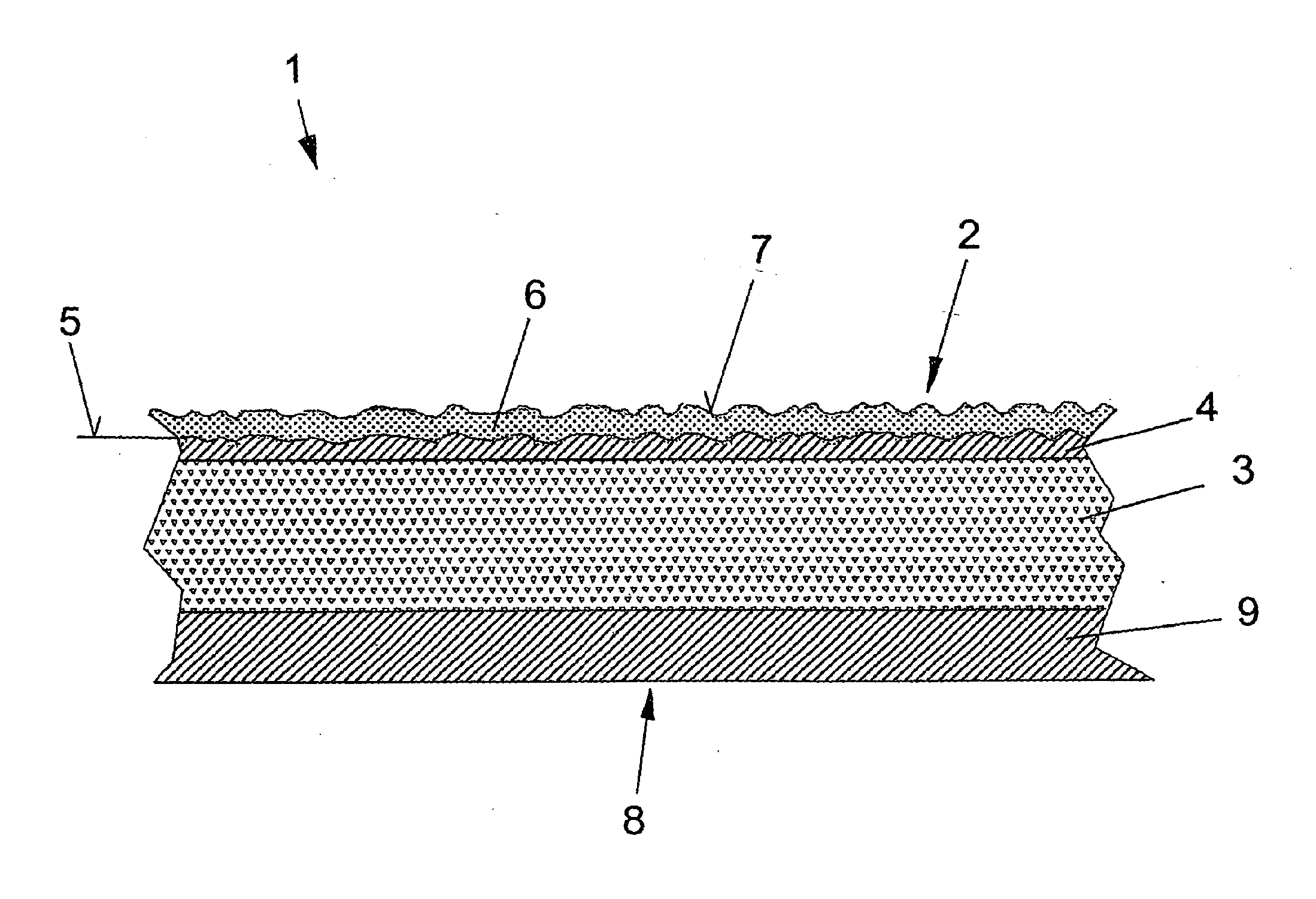
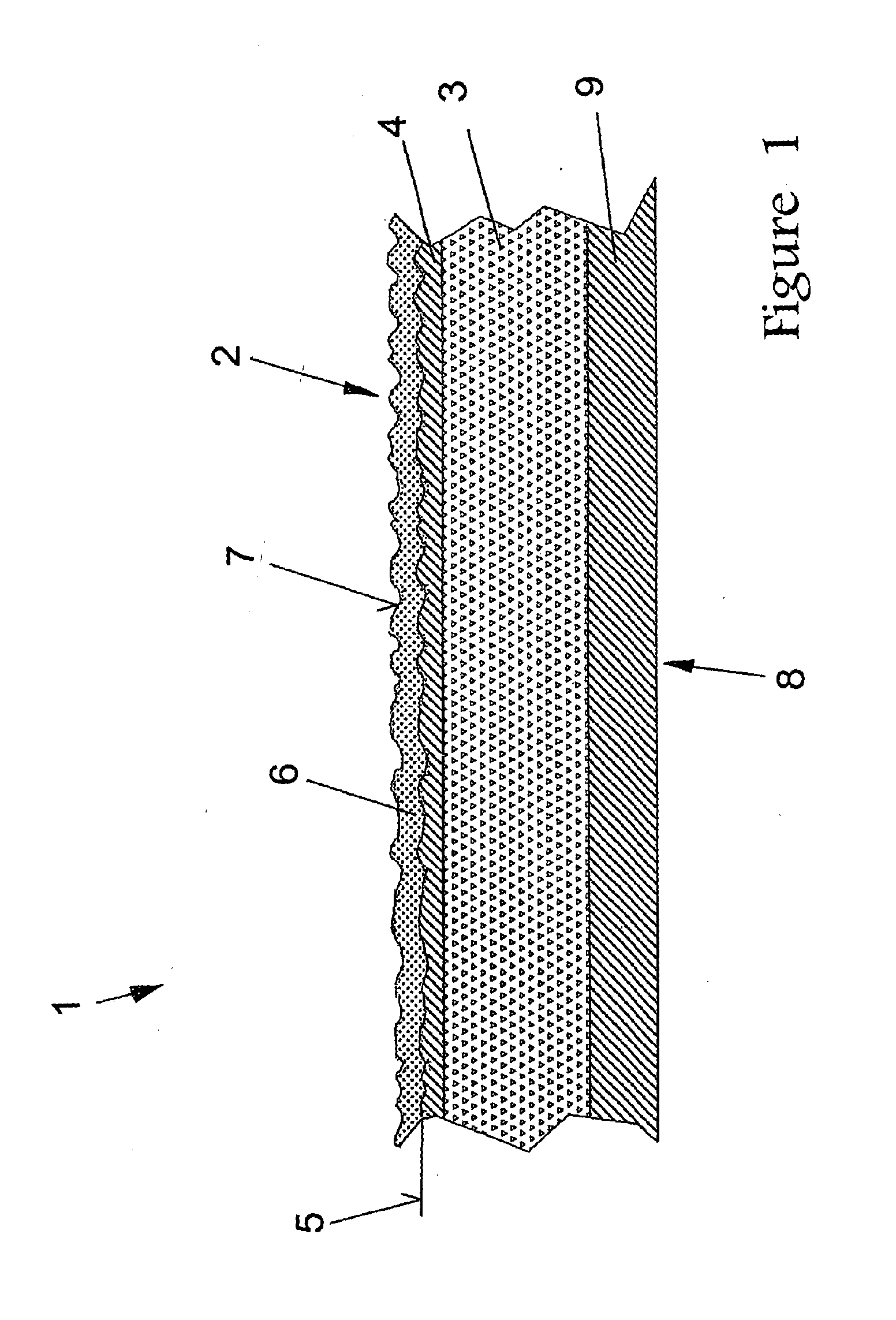
[0035]Board 1 shown in FIG. 1 is a board 1 according to the prior art. Decorative layer 4 is applied to top side 2 of core 3 made of HDF material (high-density fibreboard). Decorative layer 4 has a graphic representation 5 of an imitated material. Decorative layer 4 is provided with cover layer 6 comprising an overlay impregnated with resin. Surface structure 7, which simulates the surface of the imitated material, is embossed on the overlay. The objective is for graphic representation 5 of decorative layer 4 to be positioned exactly on top of embossed surface structure 7 of cover layer 6. In this way, the optical impression of graphic representation 5 is intended to match the tactile impression of embossed surface structure 7.

[0036]According to the prior art, decorative layer 4 is made of printed paper, which is also impregnated with resin prior to hot-pressing. The decorative paper lies directly on core 3 of the board. On underside 8 of the board, which faces away from decorative ...


PUM

PropertyMeasurementUnit
Fractionaaaaaaaaaa
Fractionaaaaaaaaaa
Fractionaaaaaaaaaa

Abstract

The invention relates to a directly laminated plate or board that is produced by hot-pressing a core with absorbent, resin-impregnated layers, wherein at least one board surface has a decorative layer with a graphic representation of the surface of an imitated material, in addition to a resin-impregnated, transparent cover layer on said decorative layer, with a relief-like reproduction of the surface structure of the imitated material, where a resinous intermediate ply is provided between the decorative layer and the core.

Description

CROSS-REFERENCE TO RELATED APPLICATIONS[0001]This application is a continuation of U.S. patent application Ser. No. 10 / 513,773, filed Sep. 14, 2005, which is a U.S. national stage application of PCT / DE03 / 01207, filed Apr. 11, 2003, which claim priority to German application no. 102 20 501.9, filed May 7, 2002, the entire disclosures of which are incorporated herein by reference.FIELD OF THE INVENTION[0002]The invention relates to a directly laminated plate or board that is produced by hot-pressing a core and absorbent, resin-impregnated layers, wherein at least one board surface has a decorative layer with a graphic representation of the surface of an imitated material, in addition to a resin-impregnated, transparent cover layer on said decorative layer, with a relief-like reproduction of the surface structure of the imitated material.BACKGROUND OF THE PRIOR ART[0003]Imitated materials include, for example, building materials, such as wood, ceramics, natural stone and artificial sto...

Claims


Application Information

Patent Timeline
IPC IPC(8): B44C1/00B32B29/02B27N3/06B32B7/10B32B27/04B32B33/00B44C5/04C08L1/00C08L93/00
CPCB32B27/04B32B29/02B44C5/0469B44C1/00Y10T428/24802Y10T428/24364Y10T428/24438Y10T156/10Y10T428/24843Y10T428/31982
Inventor EISERMANN, RALF
Owner SURFACE TECH
Why Eureka
Try Eureka