Anti-adhesion cervical dilatation stent

An anti-adhesion and cervical technology, applied in the field of medical devices, can solve the problems of great influence on the uterine cavity and inapplicability, and achieve the effect of reducing compression, preventing adhesion and achieving continuous expansion.

Pending Publication Date: 2021-04-30
JIANGSU PROVINCE HOSPITAL THE FIRST AFFILIATED HOSPITAL WITH NANJING MEDICAL UNIV
View PDF0 Cites 2 Cited by
  • Summary
  • Abstract
  • Description
  • Claims
  • Application Information

AI Technical Summary

Problems solved by technology

Both methods have a greater impact on the uterine cavity and are not suitable for patients with cervical canal adhesions or cervicoplasty

Method used


Image

  • Anti-adhesion cervical dilatation stent
  • Anti-adhesion cervical dilatation stent
  • Anti-adhesion cervical dilatation stent

Examples


Embodiment Construction

[0021] In order to have a further understanding of the purpose, structure, features, and functions of the present invention, the following detailed descriptions are provided in conjunction with the embodiments.

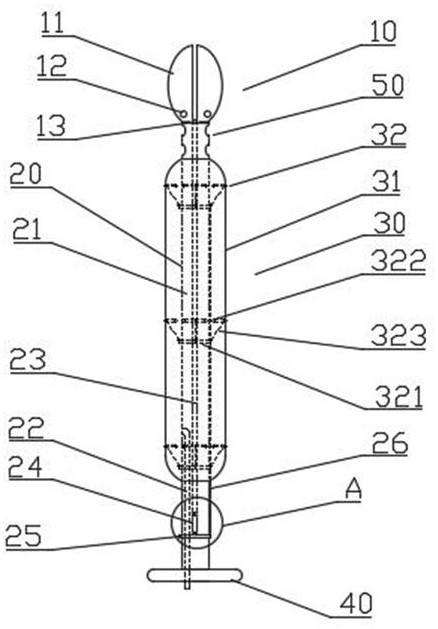
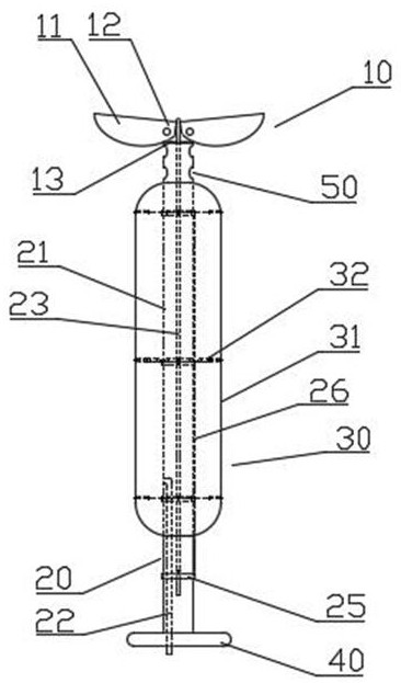
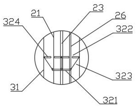
[0022] Please refer to figure 1 , figure 2 and image 3 , figure 1 It is a schematic diagram of the overall structure of an anti-adhesion cervical dilation stent of the present invention, figure 2 It is a schematic structural view of the working state of an anti-adhesion cervical dilation stent of the present invention, image 3 It is a structural schematic diagram of an expansion ring assembly of an anti-adhesion cervical expansion stent of the present invention. Figure 4 It is a structural schematic diagram of a stop ring and nearby components of an anti-adhesion cervical dilation stent of the present invention. Figure 5 It is a side structure schematic diagram of a limit pin of an anti-adhesion cervical dilation stent of the present invention.

[0023] Su...


PUM


Abstract

The invention provides an anti-adhesion cervical dilatation stent. The anti-adhesion cervical dilatation stent comprises a cervix uteri opening limiting assembly, a supporting assembly and a cervical dilatation assembly. The cervix uteri opening limiting assembly is connected to the head end of the supporting assembly, and the cervix uteri expanding assembly wraps the outer side of the support assembly. The cervical dilation assembly comprises an elastic bag body and a dilation ring assembly, the expansion ring assembly is arranged on the support assembly in a sleeving mode and connected with the elastic bag body, and the elastic bag body covers the outer side of the dilation ring assembly in a sealed mode. The cervical dilatation stent can play a role in continuous cervix uteri dilation, hematocele in the uterine cavity can be fully drained after a patient with cervical dysplasia is subjected to a cervix uteri forming operation, and formed cervix uteri is not prone to closing after a period of time.

Description

technical field [0001] The invention relates to the technical field of medical devices, in particular to an anti-adhesion cervical dilation stent. Background technique [0002] Clinically, some patients need cervical canal adhesion separation due to cervical canal adhesion, and some patients need cervical plastic surgery due to cervical dysplasia. After the operation is completed, cervical adhesion is often prone to reoccurrence, resulting in unsatisfactory surgical results. The methods used in the past include placing an intrauterine device, relying on the tail wire of the IUD to penetrate the cervical canal to achieve isolation; or placing a small double-lumen urinary catheter. The tail wire of the IUD is too thin, and the isolation effect is not good; the balloon of the double-lumen catheter must be filled with water to be placed in the uterine cavity without falling off, and the placement time is often only a few days. Both methods have a greater impact on the uterine c...

Claims


Application Information

Patent Timeline
IPC IPC(8): A61M29/04A61M25/10A61M1/00
CPCA61M25/0068A61M25/10A61M29/02A61M2210/1433A61M2210/005
Inventor 陆静韩素萍周德兰
Owner JIANGSU PROVINCE HOSPITAL THE FIRST AFFILIATED HOSPITAL WITH NANJING MEDICAL UNIV
Why Eureka
Try Eureka