Automatic test system with synchronized instruments

a test system and synchronized technology, applied in the direction of instruments, individual semiconductor device testing, semiconductor/solid-state device testing/measurement, etc., can solve the problem of additional challenge for test system designers, the practical limit of the frequency of a reference clock

Active Publication Date: 2006-06-08
TERADYNE
View PDF25 Cites 26 Cited by
  • Summary
  • Abstract
  • Description
  • Claims
  • Application Information

AI Technical Summary

Benefits of technology

[0019] In another aspect, the invention relates to a test system of the type having a plurality of instruments. The test system includes a reference clock generator providing a reference clock. A first instrument comprises a first local clock generator coupled to the reference clock generator and providing a first local clock generated from the reference clock and a first control circuit storing programmed commands for the plurality of instruments. A second instrument comprises a second local clock generator coupled to the reference clock generator and providing a second local clock generated from the reference clock; a second control circuit having an input and an output, the second control circuit asserting the output at a time specified by a time value provided at the input to the second control circuit; and functional circuitry having a control input coupled to the output of the second control circuit, the functional circuitry executing a function in response to a value asserted at its control input. The test system also has a network between at least the first instrument and the second instrument, the network carrying a message that includes a time value, wherein the first control circuit is coupled to the network to provide the time value in the message and the second control circuit is coupled to the network to receive the time value at its input.

Problems solved by technology

Increasing complexity of semiconductor chips has required that automatic test equipment also generate and measure more complex signals.
However, assembling a test system from separate instruments creates an additional challenge for test system designers because the actions of the various instruments must be coordinated.
There is often a practical limit to the frequency of a reference clock that can be reliably fanned out to many instruments in a test system, which can be undesirable.
Lower frequency clocks have longer periods and therefore provide less timing resolution.
Designing and building interpolators in a test system therefore presents complexities not present when times are measured relative to a digital clock.

Method used


Image

  • Automatic test system with synchronized instruments
  • Automatic test system with synchronized instruments
  • Automatic test system with synchronized instruments

Examples


Embodiment Construction

[0029] This invention is not limited in its application to the details of construction and the arrangement of components set forth in the following description or illustrated in the drawings. The invention is capable of other embodiments and of being practiced or of being carried out in various ways. Also, the phraseology and terminology used herein is for the purpose of description and should not be regarded as limiting. The use of “including,”“comprising,” or “having,”“containing,”“involving,” and variations thereof herein, is meant to encompass the items listed thereafter and equivalents thereof as well as additional items.

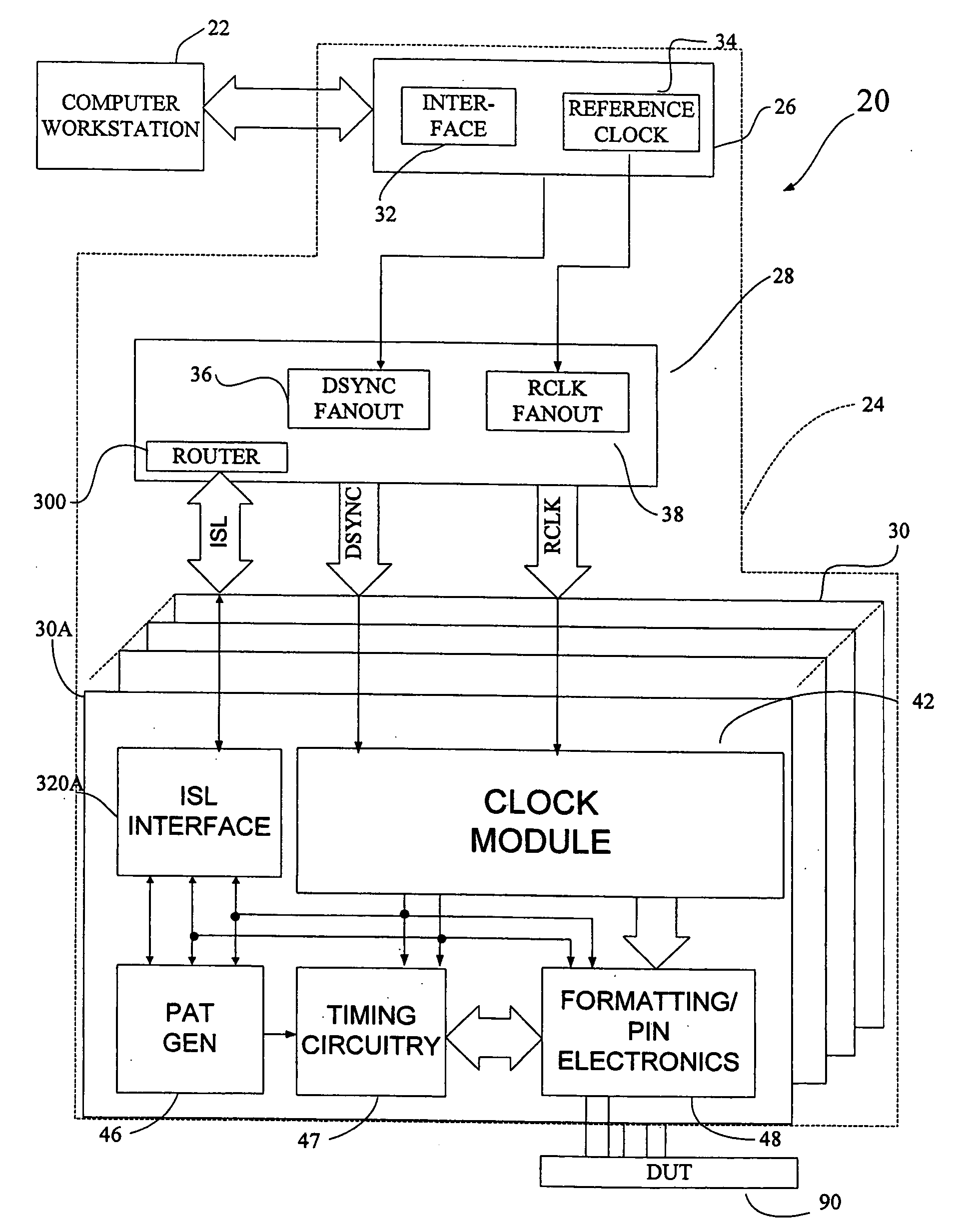
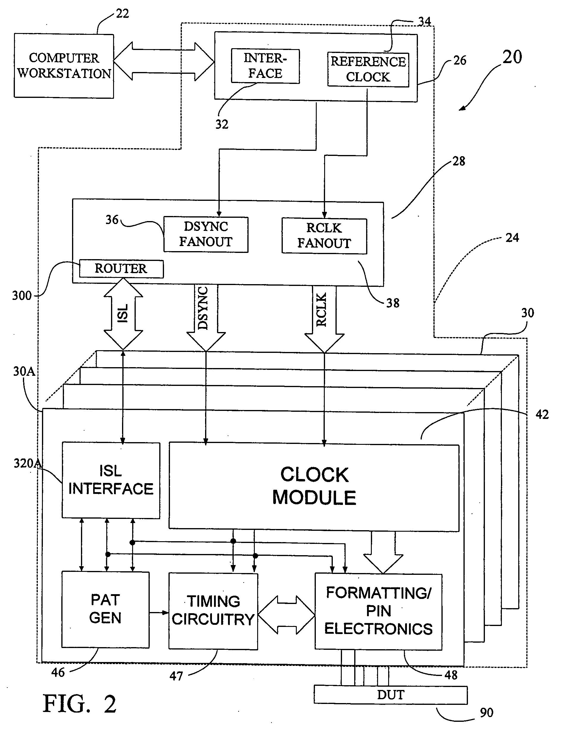
[0030] Referring more specifically to FIG. 2, an embodiment of the invention is described in relation to a semiconductor tester, generally designated 20, that includes a computer workstation 22, and a testhead 24 (in phantom). The testhead houses a plurality of electronic board assemblies for generating and measuring test signals, including central card 26, di...


PUM


Abstract

A test system with multiple instruments. Some instruments act as controller instruments and others act as controlled instruments. Each instrument includes a clock generator that synthesizes one or more local clocks from a reference clock. The reference clock is a relatively low frequency clock that can be inexpensively but accurately generated and distributed to all of the instruments. A communication link between instruments is provided. Timing circuits within instruments that are to exchange time information are synchronized to establish a common time reference. Thereafter, instruments communicate time dependent commands or status messages asynchronously over the communication link by appending to each message a time stamp reflecting a time expressed relative to the common time reference. The test system includes digital instruments that contain pattern generators that send command messages to analog instruments, which need not include pattern generators. The architecture simplifies design of analog instruments and avoids redesign of analog instrument as pattern rates of digital instruments change.

Description

RELATED APPLICATIONS [0001] This application claims priority under 35 U.S.C. § 119(e) to U.S. Provisional Application Ser. No. 60 / 630,111, entitled “INSTRUMENT SYNCHRONIZATION FOR AUTOMATIC TEST EQUIPMENT,” filed on Nov. 22, 2004, which is herein incorporated by reference in its entirety. [0002] This case is related to “INSTRUMENT WITH INTERFACE FOR SYNCHRONIZATION IN AUTOMATIC TEST EQUIPMENT,” filed Feb. 22, 2005, which is incorporated by reference herein in its entirety.FIELD OF THE INVENTION [0003] The invention relates generally to automatic test equipment and more particularly to control of instruments within a test system. BACKGROUND OF THE INVENTION [0004] Semiconductor devices are tested, often multiple times, during their manufacture. A piece of automatic test equipment, referred to as a “tester,” is used to generate test signals that stimulate a device under test (DUT) and to measure the response. The tester determines whether a DUT is operating properly by comparing the r...

Claims


Application Information

Patent Timeline
Patent Type & Authority Applications(United States)
IPC IPC(8): G01R31/28
CPCG01R31/319G01R31/31907G01R31/26G01R31/3183H01L22/00
Inventor REICHERT, PETER A.NGUYEN, THIEN D.
Owner TERADYNE
Why Eureka
Try Eureka