
Clothing dryer

a dryer and cloth technology, applied in the field of cloth dryers, can solve the problems of reducing the flow rate of hot air discharged through difficult to discharge the impurities adhered to the inner peripheral surface of the hot air outlet duct to the outside with such a blowing force, and wasting heat. , to achieve the effect of facilitating the removal of impurities accumulated

Inactive Publication Date: 2006-06-15
SAMSUNG ELECTRONICS CO LTD
View PDF3 Cites 7 Cited by
  • Summary
  • Abstract
  • Description
  • Claims
  • Application Information

AI Technical Summary

Benefits of technology

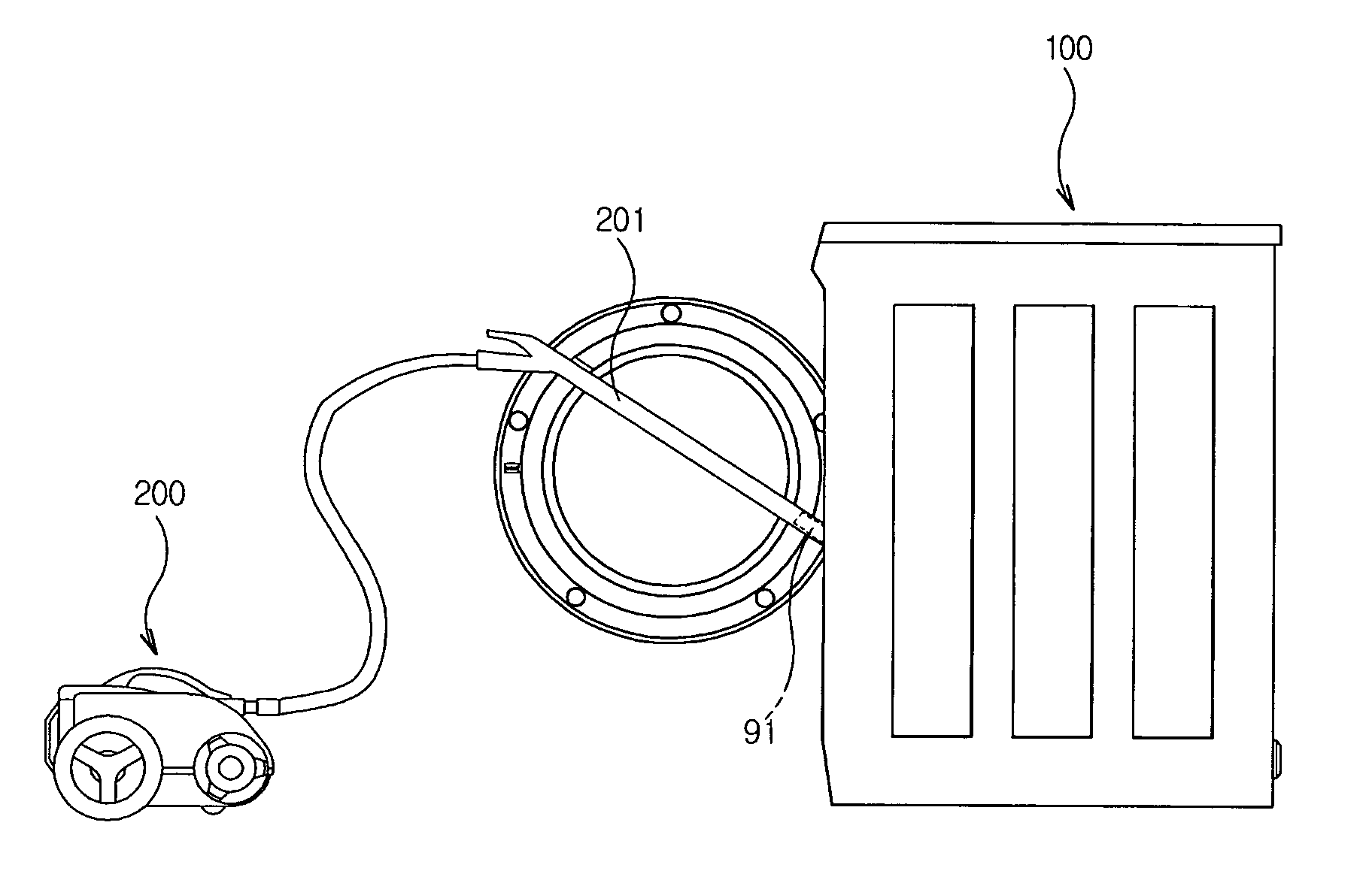
The present invention provides a clothing dryer with a hot air outlet duct that can be easily cleaned. The dryer includes a connecting unit that allows for the removal of impurities accumulated in the hot air outlet duct using an external suction force. The connecting unit can be connected to an external suction device, such as a vacuum cleaner, to effectively clean the hot air outlet duct. The dryer also includes a grill member, a hot air guiding section, a filter, and a filter fitting slot to allow for the separation and removal of impurities from the hot air flow. The invention provides a more efficient and effective way to clean the hot air outlet duct of a clothing dryer.

Problems solved by technology

In the case of the conventional clothing dryer configured as stated above, however, if a flow rate of the hot air, passing through the drying tub, is excessively high, the hot air fails to sufficiently transfer its heat to laundry contained in the drying tub and thus is discharged to the outside at high temperature, resulting in a waste of heat.
Another problem of the conventional clothing dryer is that minute impurities, such as dust, lint, etc., not captured by the filter, are accumulated in the hot air outlet duct with the passage of time, thereby reducing the flow rate of the hot air discharged via the hot air outlet duct.
Although it is preferable to remove the impurities accumulated in the hot air outlet duct using a blowing air, since the blowing force of the blowing fan provided at the conventional clothing dryer is set only to dry the laundry contained in the drying tub, it is difficult to discharge the impurities adhered to the inner peripheral surface of the hot air outlet duct to the outside with such a blowing force.

Method used


Image

  • Clothing dryer
  • Clothing dryer
  • Clothing dryer

Examples


Embodiment Construction

[0026] Reference will now be made in detail to an exemplary embodiment of the present invention illustrated in the accompanying drawings, wherein like reference numerals refer to like elements throughout. The embodiment is described below to explain the present invention by referring to the figures.

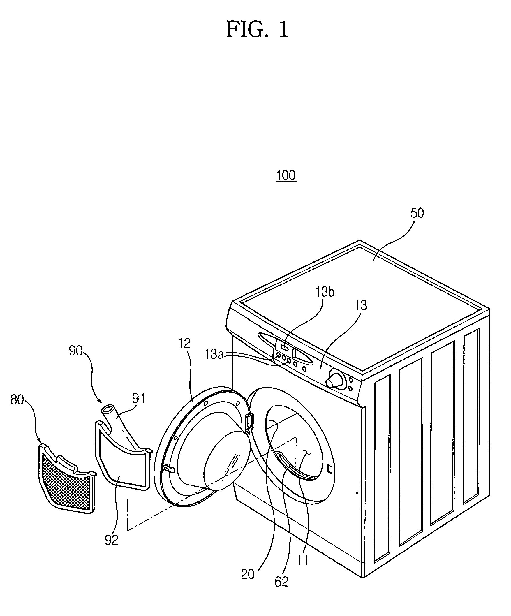
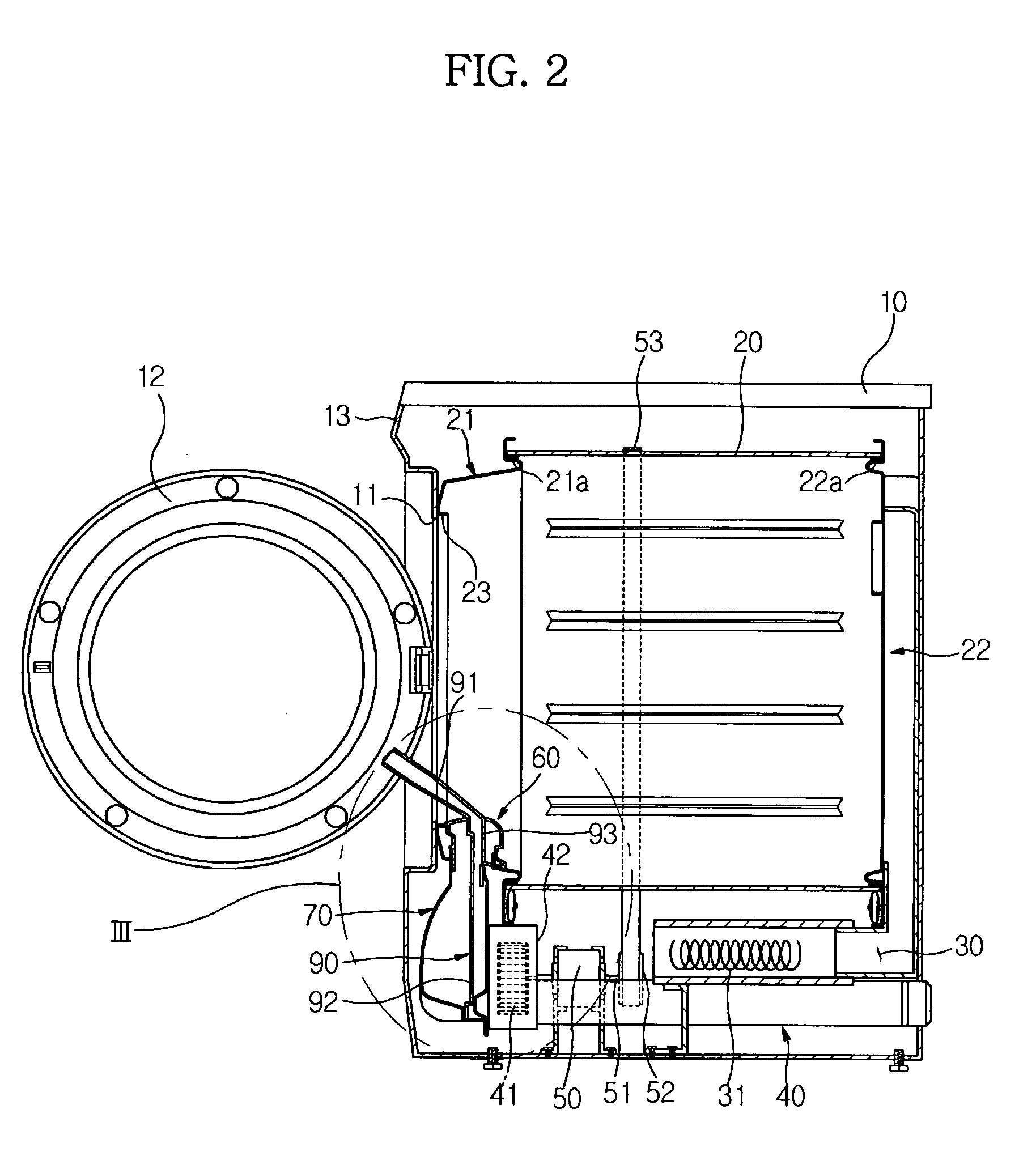
[0027]FIG. 1 is perspective view of a clothing dryer consistent with an exemplary embodiment of the present invention, and FIG. 2 is a side sectional view of the clothing dryer.

[0028] Referring to FIGS. 1 and 2, the clothing dryer 100 of the present invention comprises a housing 10 forming an external appearance of the clothing dryer, a cylindrical drying tub or drum 20 rotatably disposed in the housing 10, a hot air inlet duct 30 to introduce hot air into the drying tub 20, and a hot air outlet duct 40 to discharge the hot air, coming from the drying tub 20, to the outside.

[0029] The housing 10 is provided at a front side thereof with an opening 11 to put wet laundry into or take laun...


PUM


Abstract

A clothing dryer capable of removing impurities, such as dust, accumulated in a hot air outlet duct thereof. The clothing dryer includes a drying tub to dry laundry contained therein using hot air supplied thereto, a hot air outlet duct to discharge the hot air, coming from the drying tub, to the outside, and a connecting unit to connect an external suction device to the hot air outlet duct. Accordingly, impurities, such as dust, accumulated in the hot air outlet duct can be removed by a suction force of the suction device, thereby enabling the cleaning of the hot air outlet duct.

Description

CROSS-REFERENCE TO RELATED APPLICATION [0001] This application claims priority from Korean Patent Application No. 2004-105636, filed on Dec. 14, 2004 in the Korean Intellectual Property Office, the disclosure of which is incorporated herein by reference. BACKGROUND OF THE INVENTION [0002] 1. Field of the Invention [0003] The present invention relates to a clothing dryer and, more particularly, to a clothing dryer comprising a connecting unit for use in the cleaning of a hot air outlet duct that guides hot air to the outside. [0004] 2. Description of the Related Art [0005] In general, a clothing dryer is designed forcibly to blow hot air into a drying tub to dry wet laundry contained in the drying tub. Such a clothing dryer is provided with a heater and blowing fan forcibly to circulate the hot air to the drying tub, thereby drying the laundry. [0006] A conventional clothing dryer, as disclosed in Korean Patent Registration No. 10-446764, comprises a housing provided at its front sid...

Claims


Application Information

Patent Timeline
Patent Type & Authority Applications(United States)
IPC IPC(8): F26B13/30F26B11/02
CPCD06F58/22D06F58/04D06F58/26D06F58/10Y02B40/00
Inventor CHUNG, YOUNG SUKLEE, JUNG HO
Owner SAMSUNG ELECTRONICS CO LTD
Learn More