Dripless purification manifold and cartridge

a technology of water purification manifold and cartridge, which is applied in the direction of filtration separation, separation process, treatment involving filtration, etc., can solve the problems of flow control valve not being provided at either the manifold or the cartridge, and the need to deal

Inactive Publication Date: 2006-06-15
MAGNUSSON JAN H +2
View PDF36 Cites 36 Cited by
  • Summary
  • Abstract
  • Description
  • Claims
  • Application Information

AI Technical Summary

Benefits of technology

[0006] It is therefore a primary object of the invention to provide a cartridge based water purification and filtration system that prevents drainage from the supply and return lines upon removing a treatment cartridge.
[0009] It is a further object of the invention to provide a manifold having a projecting surface or bayonet fitting which contains a number of O-ring seals and which fitting mounts to a mating outlet recess at the cartridge which is backed by additional seals at the cartridge to prevent bypass migration of contaminants.
[0016] A one-way check valve at the manifold outlet port permits liquid out flow but prevents back flow. A tapered valve stem is normally biased to a closed condition at the manifold to mate with a seat surface and opens upon liquid outflow being directed against the valve stem. In another construction, the valve includes a split, cylindrical stem and is constructed to provide surfaces that promote non-symmetrical flow to prevent valve oscillation and nuisance audible sounds.

Problems solved by technology

A particular problem experienced with the changing of single appliance water purification / filtration cartridges is the necessity of dealing with drainage released from the supply and return lines with the release of the cartridge from a system manifold.
The sporadic frequency of the cartridge changes and attendant operator forgetfulness to the problem typically results in drainage.
That is, the maintenance personnel forget to mount a catch pan or other spill prevention appliance beneath the manifold and it becomes necessary to clean up the spill.
However, flow control valving is not provided at either the manifold or cartridge for any of the foregoing systems.

Method used


Image

  • Dripless purification manifold and cartridge
  • Dripless purification manifold and cartridge
  • Dripless purification manifold and cartridge

Examples


Embodiment Construction

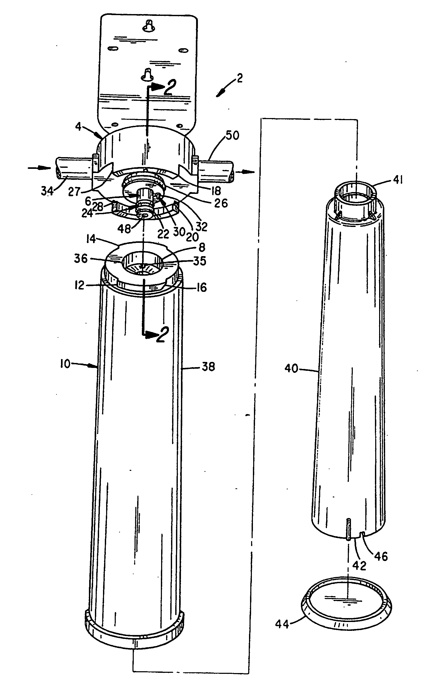
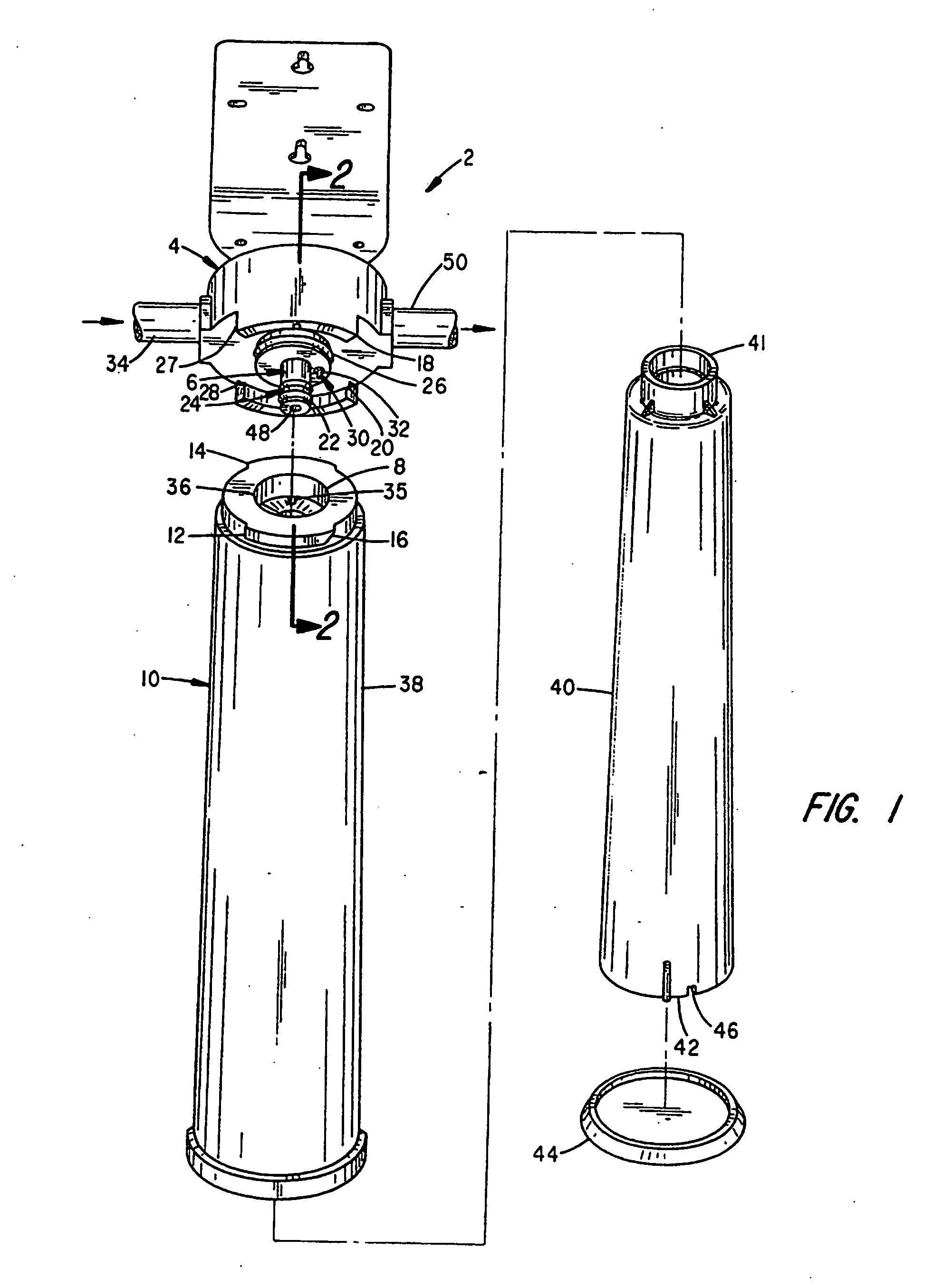
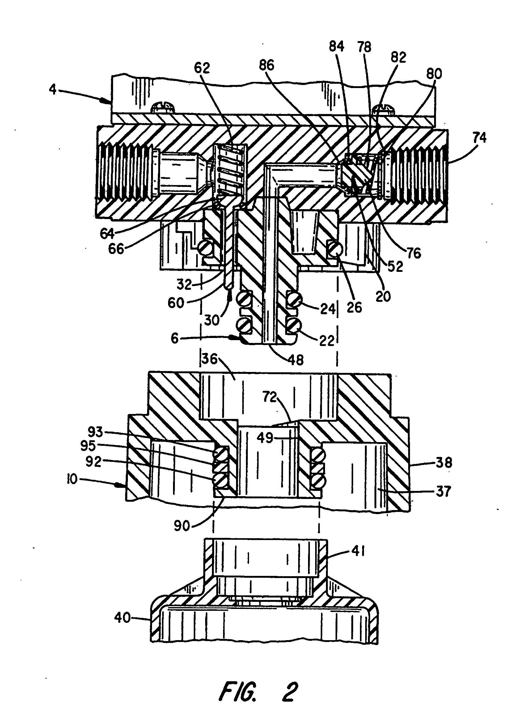
[0026] With attention to FIG. 1, an exploded assembly drawing is shown to the improved purification and filtration treatment system of the invention. The system 2 includes a supply manifold 4 having a sealed bayonet fitting 6 which mounts to a two stage recess 8 at a treatment cartridge 10. Radially displaced from the recess 8 are a pair of shoulder flanges 12, 14, which have tapered leading edges 16, that mate with a pair of interlocking flanges 18 and 20 at the manifold 4. With the mounting of the bayonet 6 into the recess B and the sealing of a number of O-rings 22, 24 and 26 mounted along the fitting 6 within the stages of the recess 8, the flanges 12, 14 are aligned to channelways 27 and 28 at the flanges 18 and 20. The cartridge 10 can then be rotated to interlock with the manifold 4, which concurrently permits flow between the manifold 4 and the cartridge 10.

[0027] Depending from one side of the bayonet fitting 6 is a stem valve assembly 30. The valve assembly 30 is configur...


PUM

PropertyMeasurementUnit
flow pressuresaaaaaaaaaa
right angleaaaaaaaaaa
lengthaaaaaaaaaa

Abstract

A cartridge based water purification and filtration system which permits cartridge changes without drainage at the input and output ports. Interlocking flanges at the manifold and cartridge lock the cartridge to the manifold and raised surfaces at the cartridge operate the inlet valve with a rotational seating of the cartridge. A spring biased inlet valve depends from a supply manifold input port and cooperates with the filter cartridge to prevent forward flow until the cartridge is seated to the manifold. The check valve includes a split stem which prevents chatter with valve operation. A check valve at the output port cooperates with a sealed bayonet fitting that mates to a concentric outlet port at the cartridge to prevent back flow with cartridge removal.

Description

[0001] This application is a divisional of application Ser. No. 10 / 983,959, filed on Nov. 8, 2004; which is a continuation of application Ser. No. 09 / 999,537, filed Nov. 15, 2001, now abandoned; which is a continuation of application Ser. No. 29 / 101,631, filed Mar. 8, 1999, now U.S. Pat. No. D-455,814; which is a continuation of application Ser. No. 08 / 984,893, filed Dec. 4, 1997, now U.S. Pat. No. 6,027,644, issued Feb. 22, 2000; which is a divisional of application Ser. No. 08 / 695,134, filed Aug. 8, 1996, now U.S. Pat. No. 5,753,107, issued May 19, 1998, the disclosure of which is herein incorporated by reference.BACKGROUND OF THE INVENTION [0002] The present invention relates to water purification and filtration systems and, in particular, to a disposable cartridge system having a manifold which cooperates with the cartridge to interrupt the supply and return lines during cartridge changes to prevent drainage from the supply system. [0003] A particular problem experienced with th...

Claims


Application Information

Patent Timeline
Patent Type & Authority Applications(United States)
IPC IPC(8): B01D21/24B01D35/153C02F1/00C02F1/28
CPCB01D35/153B01D2201/4015C02F1/003C02F1/28C02F1/283C02F2201/006C02F2307/04B01D35/306
Inventor MAGNUSSON, JAN H.LONNEMAN, ALANBOTTS, DAVID M.
Owner MAGNUSSON JAN H
Why Eureka
Try Eureka