
Color wheel and its manufacturing method

a technology of color wheel and manufacturing method, applied in the field of color wheel, can solve the problems of color filter escaping, seam generation between two adjacent color films, and inability to reduce the adhesion strength between two adjacent filter films, so as to reduce the risk of escaping

Inactive Publication Date: 2006-06-15
ASIA OPTICAL CO INC
View PDF7 Cites 19 Cited by
  • Summary
  • Abstract
  • Description
  • Claims
  • Application Information

AI Technical Summary

Benefits of technology

[0007] It is therefore an object of the claimed invention to provide a color wheel and its manufacturing method. The color wheel reduce the risk of escaping from the motor as the motor is rotating in a high speed to solve conventional problem.
[0014] In contrast to prior art, the present invention color wheel comprises a positioning ring which is stuck to the color filter. Then the positioning ring is adhered to the rotating disc of the motor, avoiding a direct contact between the color filter and the rotating disc. In other words, the color filter is stuck to the rotating disc, but adhered to the positioning ring which is affixed to the motor instead. In process of adhering the color wheel onto the rotating disc by heating, the positioning ring absorbs a stress resulting from imbalance expansion of the rotating disc and the color filter. Because the stress applied on the seam between the two adjacent filter films is lowered, an adhering strength between the two adjacent filter films may not be reduced. As a result, a seam between two adjacent color films may not generate, not only meeting precision and strength requirement for assemble, but also preventing the color filter from escaping away as the color wheel is rotating.

Problems solved by technology

Because the stress applied on the seam between the two adjacent filter films is lowered, an adhering strength between the two adjacent filter films may not be reduced.
As a result, a seam between two adjacent color films may not generate, not only meeting precision and strength requirement for assemble, but also preventing the color filter from escaping away as the color wheel is rotating.

Method used


Image

  • Color wheel and its manufacturing method
  • Color wheel and its manufacturing method
  • Color wheel and its manufacturing method

Examples


Embodiment Construction

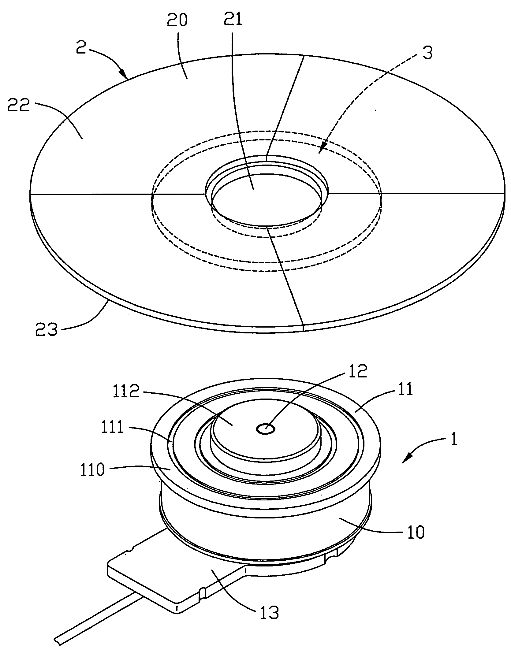
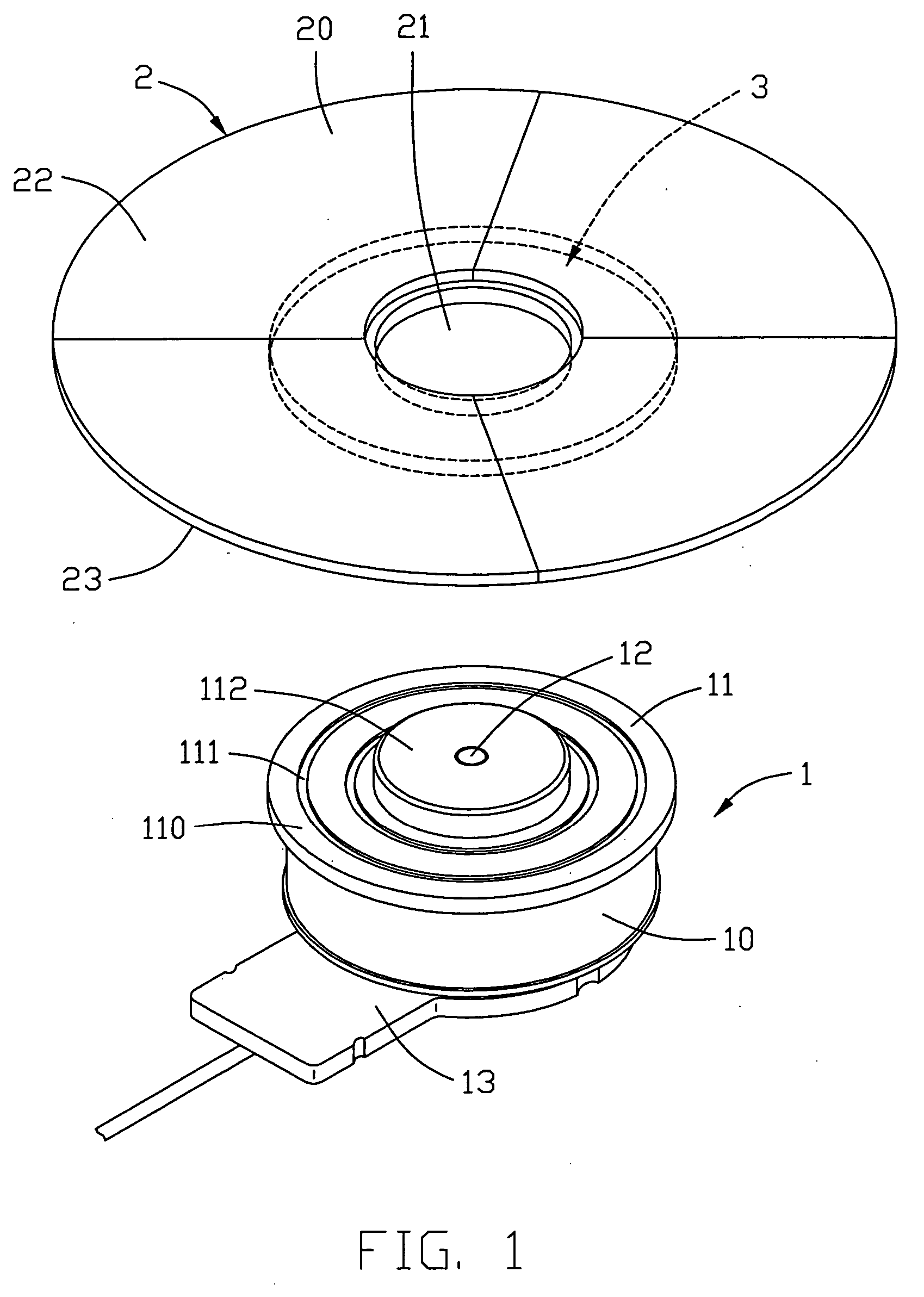
[0019] Referring to FIG. 1, a color wheel constructed in accordance with the present invention comprises a motor 1, a color filter 2, and a positioning ring 3. The motor 1 comprises a housing 10, a spindle 12, and a rotating disc 11 affixed on the spindle 12 to be rotatable in unison therewith. The spindle 12 and the rotating disc 11 are driven by the motor 12. The rotating disc 11 comprises a joint face 110 in which a circular recess 111 surrounding the spindle 12 is formed for. The rotating disc 11 further comprise a cylindrical protrusion 112 with a central bore (not labeled in FIG. 1) fit over spindle 12, for affixing the rotating disc 11 to the motor 1.

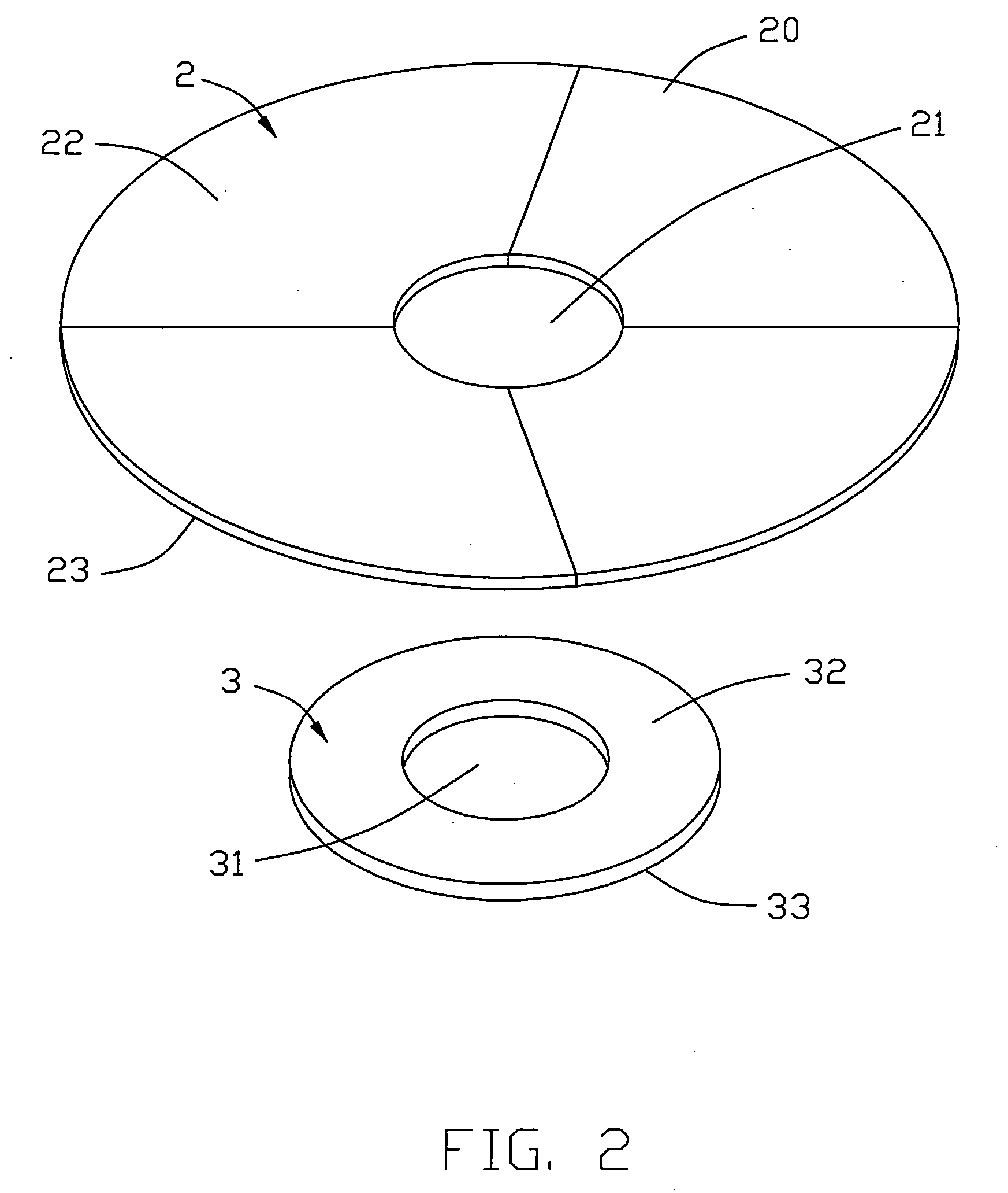
[0020] Also referring to FIG. 2, the color filter 2 is a ring-like flat member, comprising a plurality of sectors made of glass having radially extending edges jointing to each other. Radially extending joint lines are thus defined by the jointed edges of the sectors. The flat member of color filter 2 has a first surface 22 and ...


PUM


Abstract

A color wheel, for use in a Digital Light Processing (DLP), capable of preventing a color filter from escaping away is disclosed. The color wheel includes a motor having a spindle to which a rotating disc is mounted, and a filter element mounted to the rotating disc. The filter element includes a filter ring comprising a plurality of sectors having radially extending edges jointed to each other and forming a joint line between jointed edges, and a positioning ring coaxially mounted to the filter ring to hold the sectors together, the positioning ring being positioned on and fixed to the rotating disc and interposed between the filter ring and the rotating disc to fix the filter ring to the rotating disc.

Description

BACKGROUND OF INVENTION [0001] 1. Field of the Invention [0002] The present invention relates to a color wheel and related manufacture method. More particularly, the present invention relates to a color wheel for use in a Digital Light Processing (DLP), which is capable of preventing the filter film from escaping away and its manufacture method. [0003] 2. Description of the Prior Art [0004] Nowadays, there are various kinds of projectors such as a Cathode Ray Tube (CRT) type, a Liquid Crystal Display (LCD) type and a Digital Light Processing (DLP) type. The DLP projector becomes a mainstream product due to its higher brightness, shorter response period, non-noise, and smaller volume. The conventional DLP projector includes a lens for focusing light beams from a lamp to pass through a color wheel, formed by red, green, blue color filter films. Finally, the light beams are projected on a Digital Micro-mirror Device, (DMD). By using such technique, the Digital Micro-mirror Device, repl...

Claims


Application Information

Patent Timeline
IPC IPC(8): G03B21/14G02B7/00
CPCG02B7/006G02B26/008G03B21/20G03B27/547H04N9/3114
Inventor JIA, YAN-JUN
Owner ASIA OPTICAL CO INC
Learn More