Method and apparatus for provisioning optical services on an optical network

a technology of optical network and optical service, applied in the field of network management, can solve the problems of complex optical connection management, complicated manner in which a service must be provided, and extensive training of optical service provisioning systems

Active Publication Date: 2006-06-15
CIENA
View PDF3 Cites 24 Cited by
  • Summary
  • Abstract
  • Description
  • Claims
  • Application Information

AI Technical Summary

Benefits of technology

[0015] A method and apparatus for provisioning optical services on an optical network is provided that includes a user interface designed to streamline the manner in which data is displayed, and through which a network manager may provision services in a more intuitive manner. The main window includes a connection tree table that allows a path to be traced through the network from a given connection using existing topological information, concatenation port information, rate information, connection ID information, and other information available at the nodes on the network. Tracing a path from a given connection enables a view of the service associated with that connection to be approximated, since it will enable the optical provisioning system to show the network manager which other connections on the network are associated with a path that passes through the selected connection. This allows the network manager to visualize how the selected connection fits into the path or path group.

Problems solved by technology

Optical connection management is quite complex, due to the different ways in which a service may be created on the optical network.
Additionally, the underlying transport mechanisms may be different which also complicates the manner in which a service must be provisioned.
Unfortunately, the optical service provisioning systems require extensive training and require the network manager to remember a significant amount of information.
Thus, it is not uncommon for it to take an experienced network manager about 30 minutes to set up one backbone connection using existing optical provisioning systems.
For example, the vendors that design optical networking equipment haven't agreed on a standard to be used for topology discovery, and there generally is limited proprietary auto-discovery.
Thus, discovery of the network topology in a network created using network elements from multiple vendors creates gaps in the system knowledge, resulting in visualization of the network that is limited at best.
The nodal data stored by the network element for the connection frequently may be quite limited, for example including a 40 character connection ID.
Since services are typically based on end-to-end connections or collections of such connections, the nodal data is of limited value to tracing existing connections through the network.
While systems exist that will allow a single path to be derived by walking a series of nodal connections and topology, these systems are limited in many ways.
In addition to the limitations associated with knowledge of the underlying network, the network manager must also contend with the complexities of describing the service that is to be created on the network.
Existing terminology and user interface designs are concomitantly complex and either require the network manager to remember a large number of acronyms for the particular connection type to be established through the network element, or require the network manager to use multiple clicks to extract the correct connection from the user interface.
Finally, within a network element it may be difficult to select the correct port or ports to handle the connection.
Port naming is relatively complex, which may make it difficult to identify the correct port or ports for an intended service.
Since the nodes may not know which port is connected to a particular destination, selecting the proper port may be difficult.
Additionally, different customers use different modes of operation which further makes it difficult to implement port selection using existing user interfaces.

Method used


Image

  • Method and apparatus for provisioning optical services on an optical network
  • Method and apparatus for provisioning optical services on an optical network
  • Method and apparatus for provisioning optical services on an optical network

Examples


Embodiment Construction

[0042] The following detailed description sets forth numerous specific details to provide a thorough understanding of the invention. However, those skilled in the art will appreciate that the invention may be practiced without these specific details. In other instances, well-known methods, procedures, components, protocols, algorithms, and circuits have not been described in detail so as not to obscure the invention.

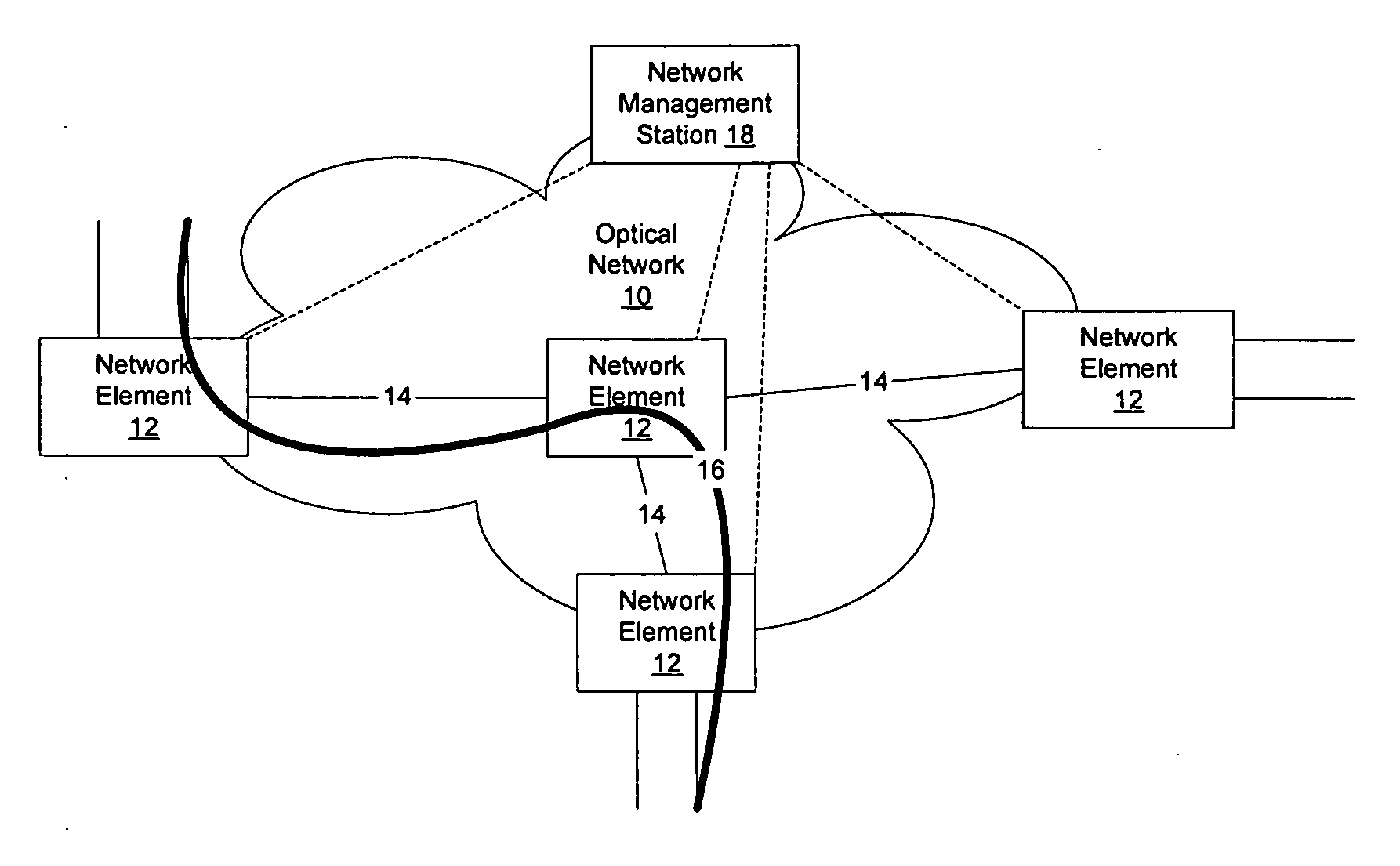
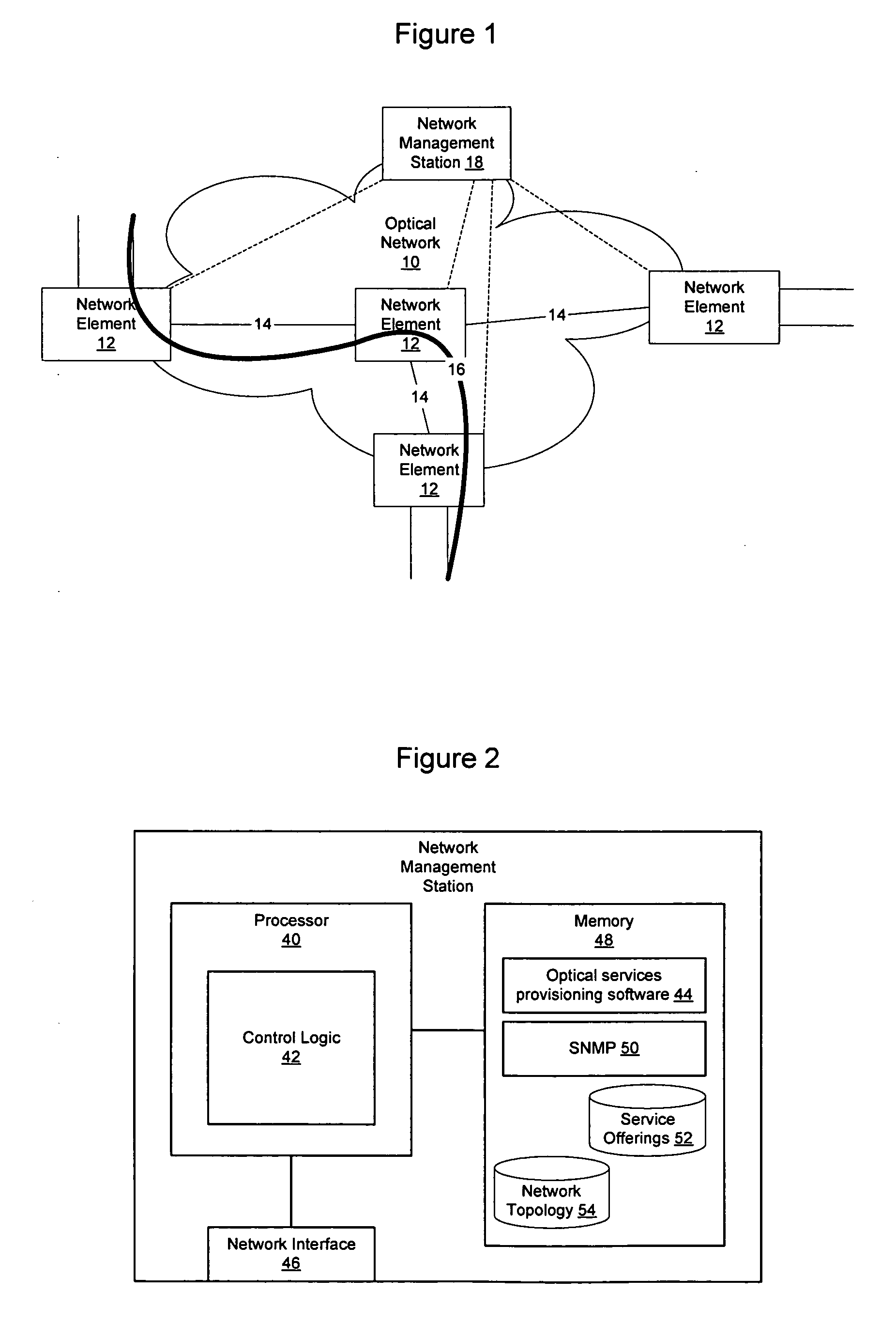
[0043]FIG. 1 illustrates an example of a portion of an optical network over which optical services may be provisioned. As shown in FIG. 1, an optical network 10 generally includes a plurality of network elements 12 interconnected by optical links 14. Services 16 may be provisioned through the optical network by defining connections through the network elements 12 that will enable data to be passed over a particular path including selected optical links. A network management station 18 may be provided to provision the optical services on the optical network.

[0044] As us...


PUM


Abstract

An optical provisioning system includes a connection tree table that allows a path to be traced through the network using connection ID, rate, and other information at the nodes on the network. As connections are built, a connection graphics panel is provided to display a representation of the network elements and topology between the network elements. Where topology is not known, it may be entered into the optical provisioning system and shown using a different graphical display element. Within a node, the connections may be built by specifying protection, routing, and optionally concatenation, via a visually intuitive user interface. Termination for the connection may be specified using a port and payload selector dialog that enables information associated with the port to be displayed to improve the port selection process and enables available channels to be viewed in a graphical manner.

Description

CROSS REFERENCE TO RELATED APPLICATIONS [0001] This application is related to and claims the benefit of U.S. Provisional Application No. 60 / 635,526, filed Dec. 13, 2004, entitled “Visuals and Method for Specifying Arbitrary Connection Routing and Protection Functions,” the content of which is hereby incorporated herein by reference.BACKGROUND OF THE INVENTION [0002] 1. Field of the Invention [0003] The present invention relates to network management and, more particularly, to a method and apparatus for provisioning optical services on an optical network. [0004] 2. Description of the Related Art [0005] Data communication networks may include various routers, switches, bridges, hubs, and other network devices coupled to and configured to pass data to one another. These devices will be referred to herein as “network elements.” Data is communicated through the data communication network by passing protocol data units, such as Internet Protocol (IP) packets, Ethernet frames, data cells, ...

Claims


Application Information

Patent Timeline
Patent Type & Authority Applications(United States)
IPC IPC(8): H04J3/14H04L12/28
CPCH04L41/12H04L43/10H04L41/34
Inventor HYNDMAN, ARNLYNK, JOHN
Owner CIENA
Why Eureka
Try Eureka