
Radio lan communication system

a radio lan and communication system technology, applied in wireless communication, data switching networks, wireless communication, etc., can solve the problems of inability to perform communication, inability to perform dynamic control for smooth communication according to situations,

Inactive Publication Date: 2006-06-15
THE TOKYO ELECTRIC POWER CO INC
View PDF5 Cites 21 Cited by
  • Summary
  • Abstract
  • Description
  • Claims
  • Application Information

AI Technical Summary

Benefits of technology

[0006] In view of the above-mentioned problem, the present invention has been made to provide a wireless LAN communication system using a CSMA method including: a base station; and plural terminals, the wireless LAN communication system being characterized in that the base station includes: a data classification function for classifying data to be transmitted to the terminals into audio data and terminal-basis ordinary data and generating downstream data communication traffic information; a queuing function for generating an ordinary data transmission queue and an audio data transmission queue by queuing the data classified by the data classification function; a communication quality control parameter setting function for setting communication quality control parameters respectively for the ordinary data transmission queue and the audio data transmission queue; a transmission and reception portion for transmitting data from the ordinary data transmission queue and from the audio data transmission queue according to the communication quality control parameters at a time of transmission; a reception data detection function for acquiring upstream communication traffic information from reception data received from each of the terminals; and a communication quality control parameter control function for dynamically adjusting each of the communication quality control parameters in the communication quality control parameter setting function, based on the downstream and upstream communication traffic information.

Problems solved by technology

For this reason, there is a problem in that when a specific one of plural terminals in the communication area of one base station frequently transmits data having a large amount of information, for example, the specific terminal exclusively uses the base station, and therefore other terminals cannot perform communications for a long period of time, making it impossible to perform dynamic control for smooth communications according to situations.

Method used


Image

  • Radio lan communication system
  • Radio lan communication system
  • Radio lan communication system

Examples


examples

[0064] When 64 terminals transmit data with CWmin being set to 15 for the base station and all the terminals, the average number of terminals which have an identical backoff time is obtained as follows: 64 / (15+1)=4.

[0065] When 64 terminals transmit data with CWmin being set to 63 for the base station and all the terminals, the average number of terminals which have an identical backoff time is obtained as follows: 64 / (63+1)=1.

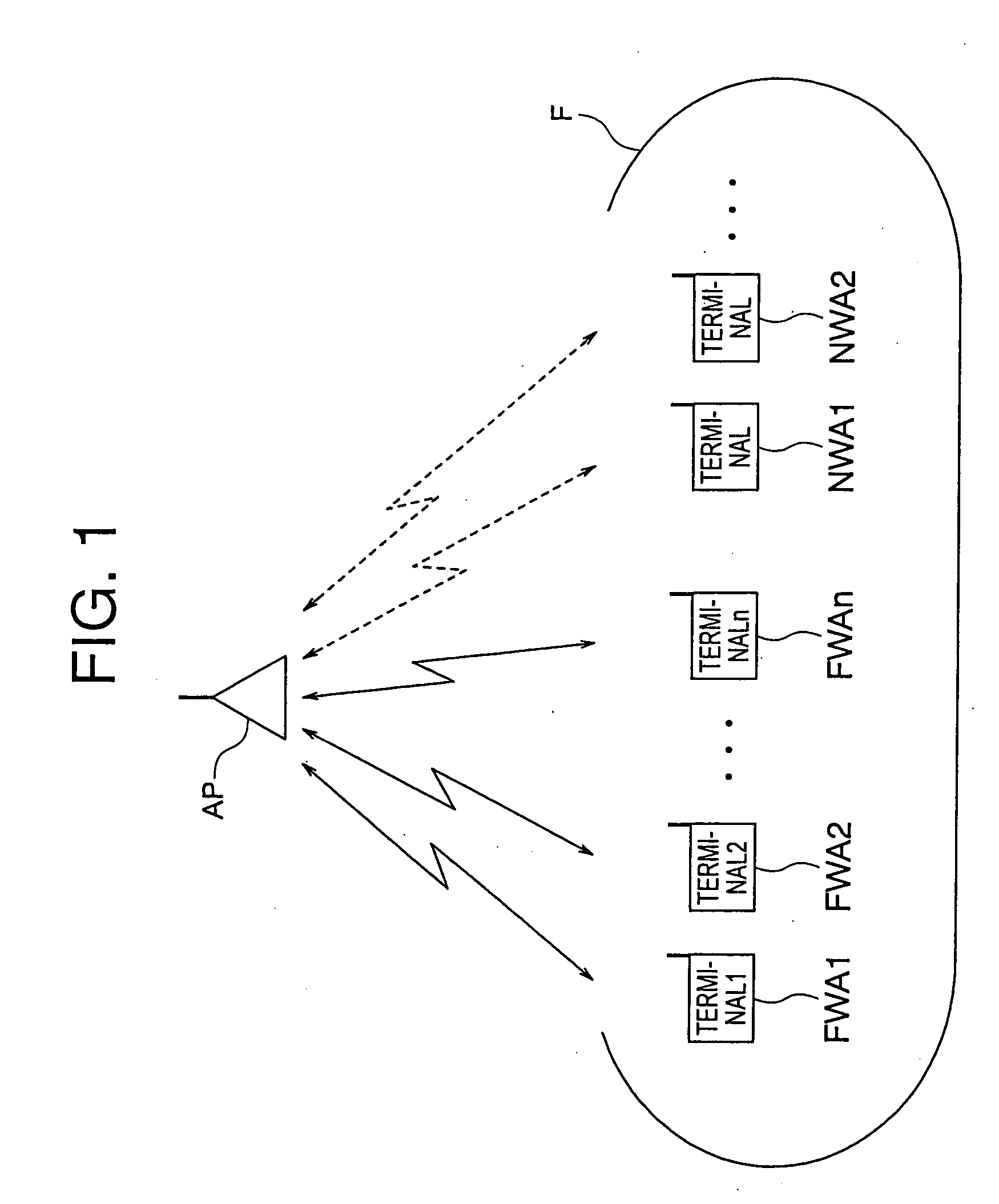
[0066] Accordingly, an M-EDCF period and an NWA period are provided in order to implement priority control among the terminals FWAs while keeping the priority of the terminals NWAs, that is, NWA terminals, lower than that of the terminals FWAs, that is, FWA terminals, and avoiding an increase in collision frequency. In the M-EDCF period, the QoS parameters of the base station AP and the terminals FWAs can be freely set. The CWmin value can also be set larger.

[0067] The QoS parameters are set, for example, as shown in FIG. 9. The QoS parameters are dynamicall...


PUM


Abstract

A base station includes: a data classification function for classifying data to be transmitted to terminals into audio data and terminal-basis ordinary data and generating downstream communication traffic information; a queuing function for generating an ordinary data transmission queue and an audio data transmission queue from the classified data; a communication quality control parameter setting function for setting communication quality control parameters for the respective queues; a transmission and reception portion for transmitting data in the queues according to the communication quality control parameters at a time of transmission; a reception data detection function for acquiring upstream communication traffic information from reception data received from each of the terminals; and a communication quality control parameter control function for dynamically adjusting each of the communication quality control parameters in the communication quality control parameter setting function, based on the downstream and upstream communication traffic information.

Description

TECHNICAL FIELD [0001] The present invention relates to a wireless LAN communication system, and more particularly to a communication priority control in a wireless LAN communication system using a CSMA (carrier sense multiple access) method. BACKGROUND ART [0002] In the CSMA method, a terminal (generally, a node) which desires to transmit data checks if communications are now being performed between a base station and another terminal. When communications are being performed, the terminal waits until the communications end. Upon the end of the communications, respective terminals which desire to transmit data start data transmission. At this time, every terminal equally has a right of transmission. If plural terminals start transmission almost at the same time, plural pieces of transmitted data collide at the base station. For this reason, the terminal which desires to transmit data monitors a communication state of the base station when transmitting a signal. If data is broken by ...

Claims


Application Information

Patent Timeline
Patent Type & Authority Applications(United States)
IPC IPC(8): H04Q7/24H04B7/26H04L12/28H04L47/56H04L47/6275H04L47/762H04W28/00H04W28/02H04W72/12H04W84/12
CPCH04L12/5693H04L47/10H04L47/14H04L47/2416H04L47/2441H04L47/32H04L47/522H04L47/56H04L47/6215H04L47/6225H04L47/626H04W72/1236H04W72/1242H04L47/50H04W28/02H04W72/543H04W72/569H04W8/04
Inventor KATSUMATA, TOSHIKAZUKOHARAGI, TAKAHIRONOMURA, HIROSHI
Owner THE TOKYO ELECTRIC POWER CO INC
Learn More