
Remote magnetic activation of hearing devices

a hearing device and magnetic activation technology, applied in the field of hearing devices, can solve the problems of inaccessible hearing devices or poor dexterity, and achieve the effects of convenient activation, less impact on the overall size of the associated hearing device, and convenient activation

Inactive Publication Date: 2006-06-15
INSOUND MEDICAL INC
View PDF19 Cites 12 Cited by
  • Summary
  • Abstract
  • Description
  • Claims
  • Application Information

AI Technical Summary

Benefits of technology

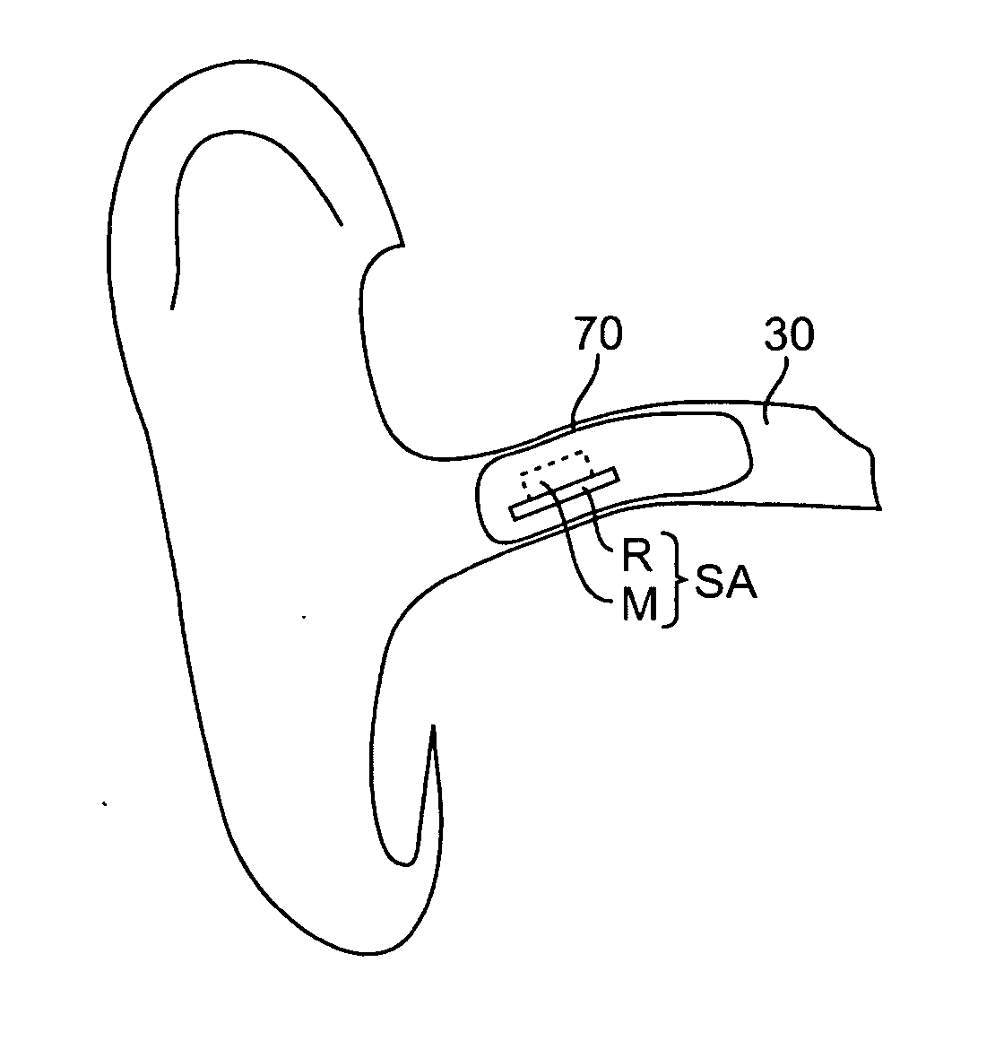
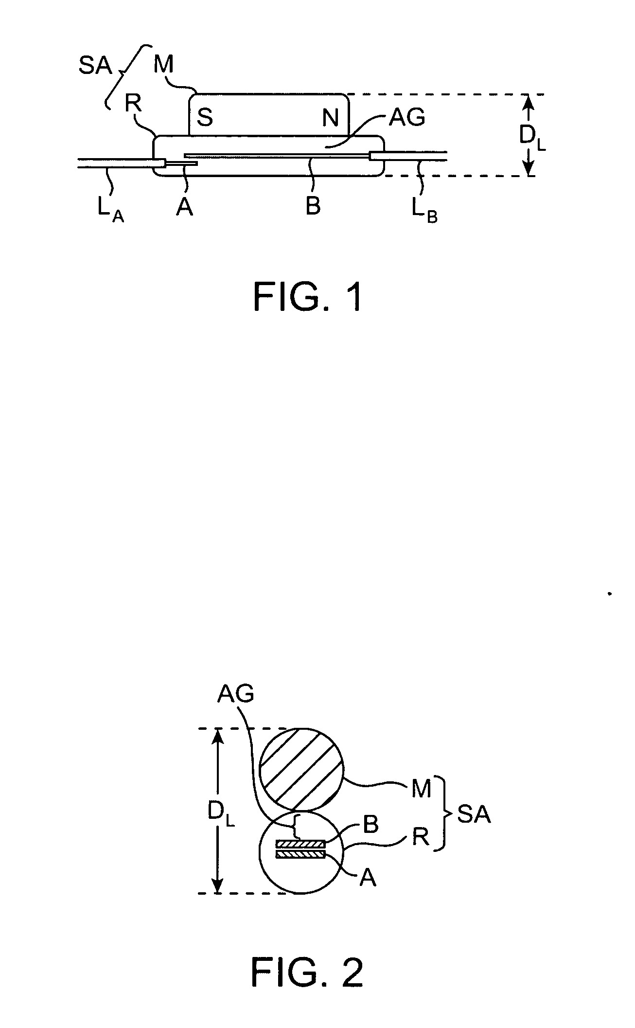
"The present invention provides a magnetic switch assembly for hearing devices that can be remotely activated by the user. The switch is highly miniaturized and has a self-contained latching mechanism. The user activation is performed by placing a hand-held magnet in proximity to the hearing device. The switch eliminates conventional miniature electromechanical switches, which are not practical for inaccessible hearing devices or persons of poor dexterity. It also eliminates conventional wireless remote control methods, which require additional circuitry and electrical power. The switch assembly comprises a miniature reed switch and a miniature latching magnet affixed directly to one of the reeds or an electrical lead wire associated with a reed. The latching magnet is placed directly on a ferromagnetic lead wire associated with a first reed of a tubular reed switch positioned horizontally in the ear canal. The miniature tubular reed switch assembly minimally impacts the overall size of the associated hearing device and is more reliable, more conveniently activated, more energy efficient, and cost effective than conventional electromechanical switches and wireless switches."

Problems solved by technology

The magnetically latchable switch eliminates conventional miniature electromechanical switches, which are manually controlled and thus not practical for inaccessible hearing devices or for persons of poor dexterity.

Method used


Image

  • Remote magnetic activation of hearing devices
  • Remote magnetic activation of hearing devices
  • Remote magnetic activation of hearing devices

Examples


example 1

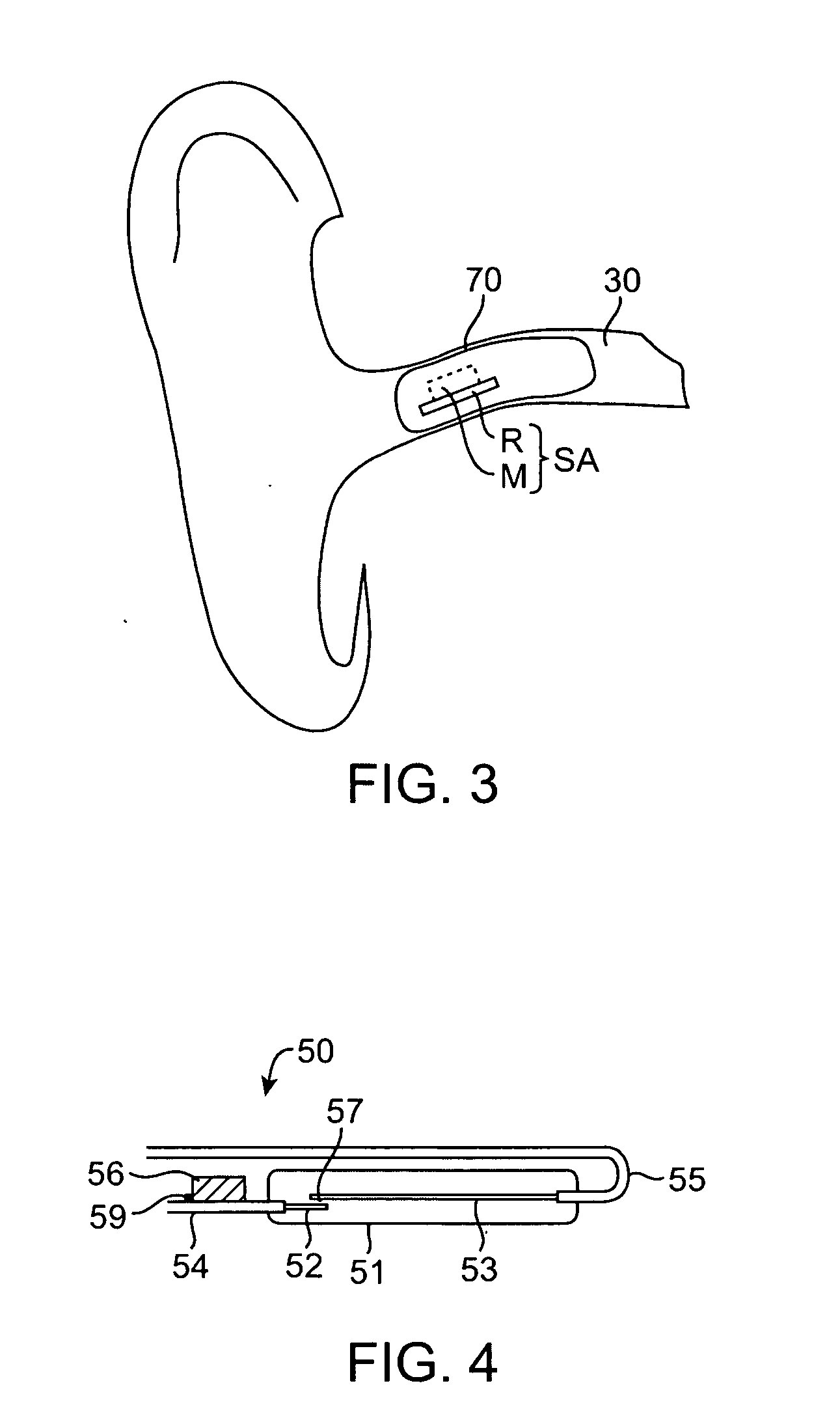
[0053] A latching reed switch assembly according to a preferred configuration of the present invention, shown in FIGS. 4-6, was constructed and compared to the prior art switch configuration shown in FIG. 1. The prior art latching reed switch assembly was based on micro-miniature reed switch model HRS-003DT manufactured by Hermetic Switch, Inc. of Chickasha, Okla. The prior art switch assembly included a latching magnet rod (M) constructed of Alnico material and positioned along the length of the tubular reed switch shown in FIG. 1. The magnet M was approximately 4.1 mm long and 1.8 mm in diameter, with a volume of approximately 10.4 mm3. The weight of the magnet was measured to be approximately 74 mg. The reed switch was approximately 5 mm long and 1.25 mm in diameter, with a volume of approximately 6.1 mm3. The reed switch weighed approximately 17 mg with a total of 11 mm of the lead wire attached. The combined volume and weight of the prior art reed switch assembly were approxima...

example 2

[0058] A control magnet was fabricated to control the latching reed switch assembly described in Example 1 above. The control magnet 60 shown in FIG. 12 was in the shape of a cylindrical rod having a length of 4.3 cm and a diameter of 5.3 mm. The body 64 of the rod was made of plastic and is attached to a pair of identical disk magnets 65 and 66. The two magnets were polarized across the length of the rod and were oriented to have opposing magnetic polarity as shown in FIG. 6. The disk magnets were made of NdFeB material sold by Radio Shack (model No. 64-1895). Each disk magnet was approximately 4.3 mm in diameter and 1.5 mm in height.

[0059] The control magnet also had two flanged stoppers (67 and 68), designed to prevent the control magnet from entering the ear canal and accidentally pushing or touching any of the components of the canal hearing device 70. Each stopper was made of polyurethane foam material but, alternatively, may be composed of any other suitable material such as...


PUM


Abstract

A magnetic switch assembly for hearing devices designed for remote activation by the user is highly miniaturized with a self-contained latching mechanism. The switch is activated and deactivated by the user via a hand-held magnet placed in proximity to the hearing device. The switch assembly includes a miniature reed switch and a miniature latching magnet affixed directly to one of the reeds or the associated lead wire. Direct attachment minimizes the air gap between the latching magnet and a reed thus enabling latching with only an extremely small magnet. The latching magnet produces a magnetic field of adequate strength to hold the reeds together in electrical contact after the air gap between the reeds is closed by the user's placement of the external hand-held magnet in proximity thereto. But the latching magnet's field is of inadequate strength for unaided closure of the air gap between the reeds. Consequently, once the reeds are closed the latching magnet prevents separation thereof until the reeds are exposed to an external magnetic field of opposite polarity and sufficient strength to overcome the field produced by the latching magnet.

Description

CROSS-REFERENCES TO RELATED APPLICATIONS [0001] This application is a continuation of U.S. patent application Ser. No. 09 / 181,533 (Attorney Docket No. 022176-000300US), filed on Oct. 28, 1998, the full disclosure of which is incorporated herein by reference.BACKGROUND OF THE INVENTION [0002] 1. Technical Field [0003] The present invention relates generally to hearing devices, and more particularly to remotely controlled hearing devices which, when worn, are not easily accessible by the hearing impaired user. [0004] 2. Description of the Prior Art [0005] Conventional hearing aids are typically equipped with one or more manually operated switches, such as an ON / OFF switch for activating or deactivating the device, or a control switch for adjusting the loudness or frequency response of the device. Improvements are continuously being made in the miniaturization of these controls in order to produce the smallest possible hearing device. Hearing devices are presently available, for exampl...

Claims


Application Information

Patent Timeline
Patent Type & Authority Applications(United States)
IPC IPC(8): H04R25/00
CPCH04R25/558
Inventor SHENNIB, ADNAN
Owner INSOUND MEDICAL INC
Learn More