

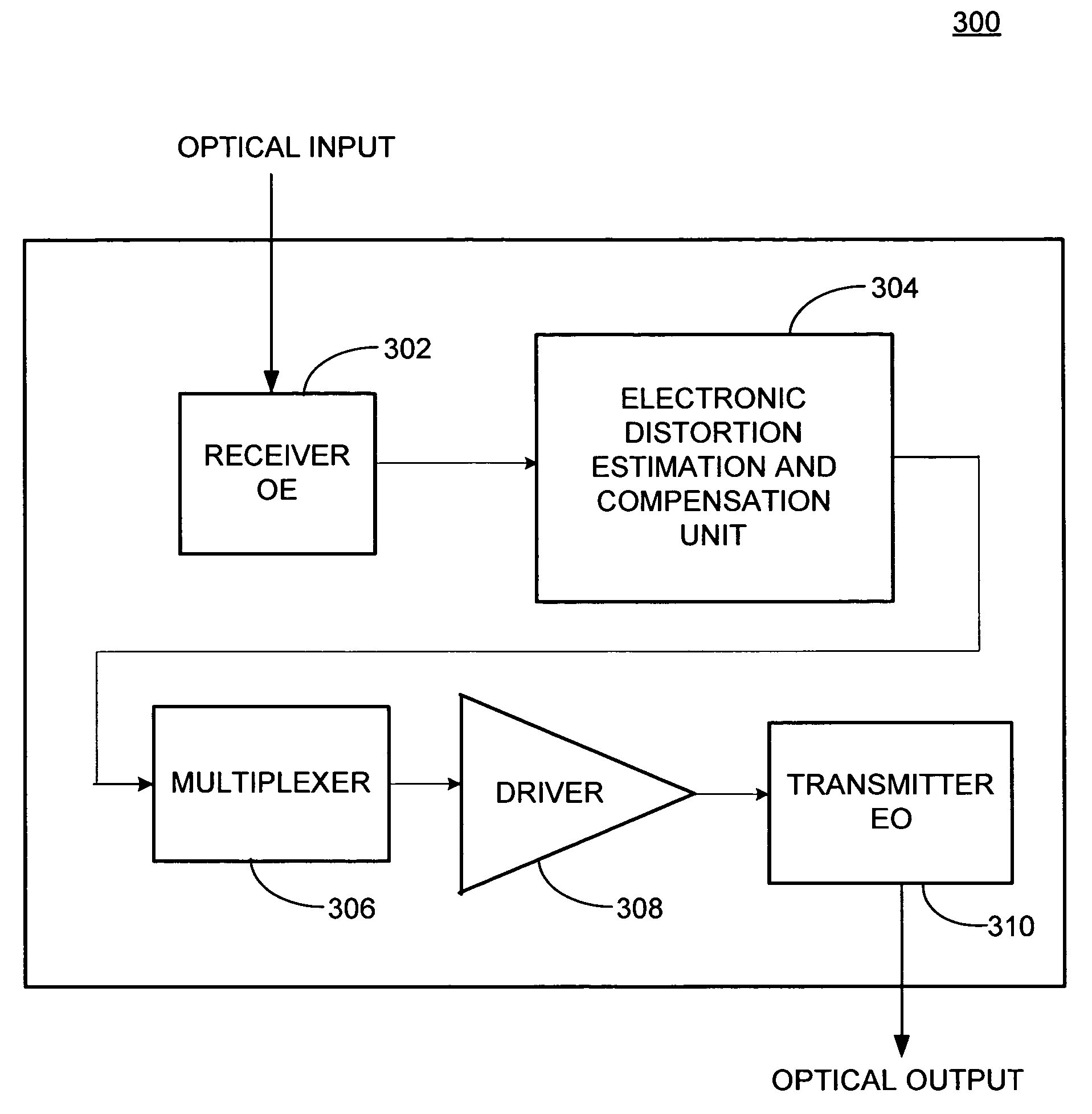
Simplified signal regenerator structure
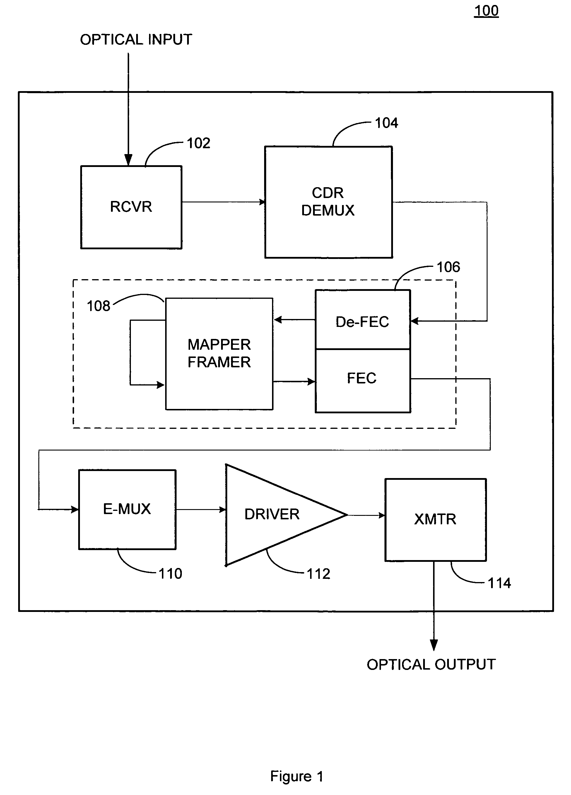
a signal regenerator and simplified technology, applied in the field of optical communication, can solve the problems of reducing the cost of conventional reconditioning nodes such as the oeo transceiver/regenerator b>100/b>, and reducing the cost of conventional reconditioning nodes compared to other network elements
- Summary
- Abstract
- Description
- Claims
- Application Information
AI Technical Summary
Problems solved by technology
Method used
Image

Examples
Embodiment Construction
[0015] In describing various embodiments of the invention, specific terminology is used for the purpose of illustration and for the sake of clarity. However, the invention is not necessarily intended to be limited to the specific terminology or particular wording so selected. It is intended that each specific term includes those technical equivalents which operate in a similar manner to accomplish a similar purpose.
[0016] One goal of optical system designers is to minimize the bit error rate (BER) of communications so as to improve the overall performance of the system. Forward error correction (FEC) is used to reduce bit error rates by allowing for the correction of errors in the transmission of the data in an effort to improve system performance. The addition of FEC to a signal boosts the effective signal-to-noise ratio (SNR), allowing signals to achieve longer propagation distance and to operate with higher levels of noise and distortion. FEC information is added to the overhead...
PUM
 Abstract
Description
Claims
Application Information