Monolithic rotational flexure bearing and methods of manufacture

a technology of rotational flexure bearings and monolithic bearings, which is applied in the direction couplings, semiconductor lasers, etc., can solve the problems of noise and vibration of mechanical roller bearings, general unsuitable applications requiring precise rotational motion, and general poor low-speed operation of conventional roller bearings. , to achieve the effect of improving the service life of the bearing, improving the service life and improving the service li

Inactive Publication Date: 2006-06-15
CALIFORNIA INST OF TECH +1
View PDF6 Cites 4 Cited by
  • Summary
  • Abstract
  • Description
  • Claims
  • Application Information

AI Technical Summary

Problems solved by technology

Mechanical roller bearings, however, typically suffer from noise and vibration resulting, for example, from the stack of tolerances between the elements and rollers disposed therebetween.
Accordingly, conventional roller bearings are generally not desirable for applications requiring precise rotational motion, e.g., with little or no axial / radial runout or small rotational angles (e.g., less than one degree) are desired.
Additionally, conventional roller bearings typically include multiple parts that may require repair or lubrication periodically.
A drawback of fluid bearings, however, includes that they generally operate poorly at low speeds and suffer from leaks or contamination of the fluid.
For example, leaks or particle contamination of the lubricating fluid may cause changes in friction, which drastically reduce the performance of the bearing.
The use of such bearings in applications that require small (or extremely limited) rotation angles, however, are generally hampered by tribology (friction-related) issues.
For example, various physical phenomena including stiction, stick-slipping, and contact wearing of the bearing are well known conundrums of conventional bearings.
These effects may become more problematic when repeatable and accurate small angles of rotations are desired of the rotational bearing.

Method used


Image

  • Monolithic rotational flexure bearing and methods of manufacture
  • Monolithic rotational flexure bearing and methods of manufacture
  • Monolithic rotational flexure bearing and methods of manufacture

Examples


Embodiment Construction

[0021] The following description is presented to enable a person of ordinary skill in the art to make and use the various aspects and examples of the inventions. Descriptions of specific materials, techniques, and applications are provided only as examples. Various modifications to the examples described herein will be readily apparent to those of ordinary skill in the art, and the general principles defined herein may be applied to other examples and applications without departing from the spirit and scope of the inventions. Thus, the present inventions are not intended to be limiting to the examples described and shown, but are to be accorded the scope consistent with the appended claims.

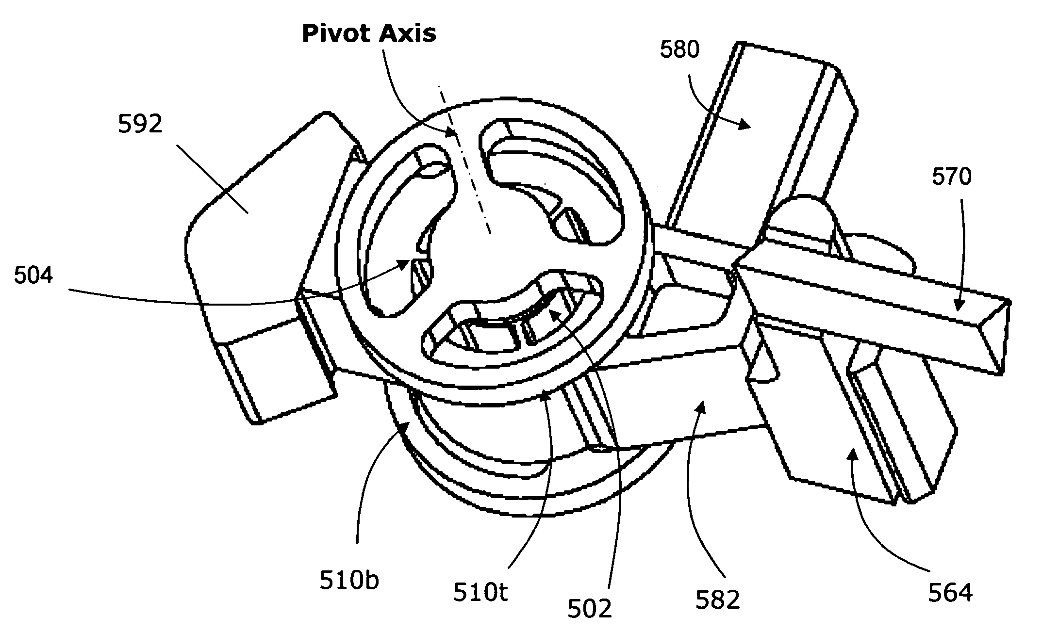
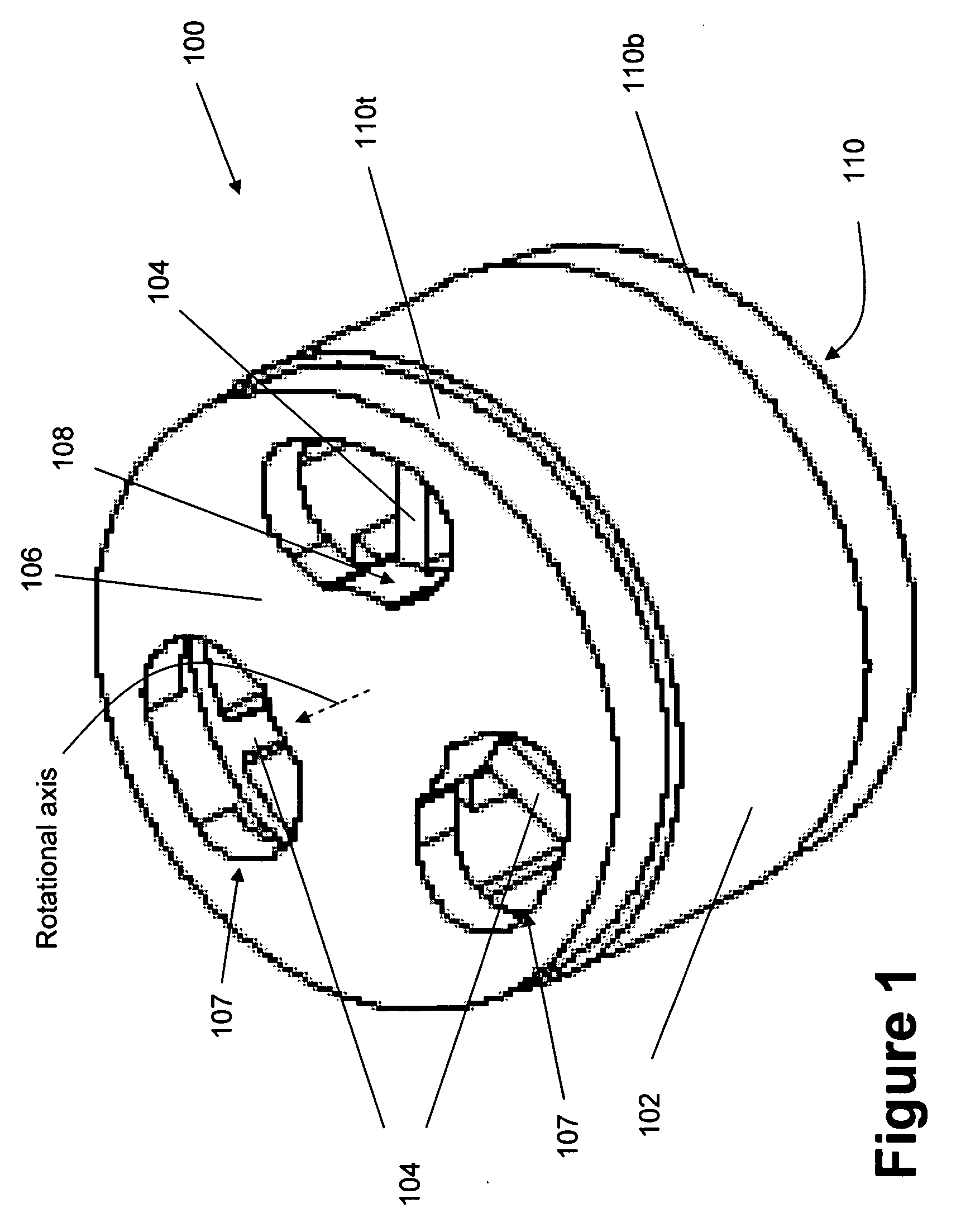
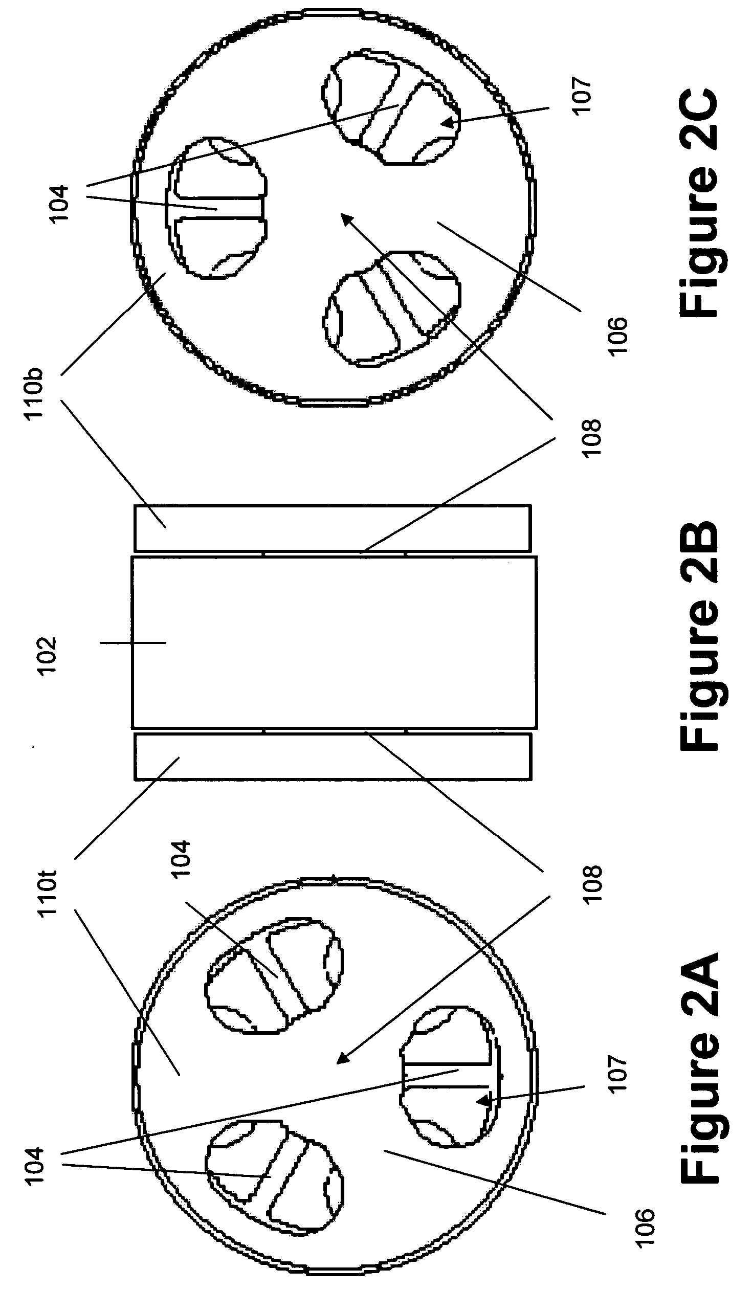
[0022] According to one aspect, an exemplary monolithic rotational flexure bearing is provided herein. Broadly speaking, flexure-based bearings are devices which operate on the principle of elastic deformation of one or more elements—typically in flexion. The flexure bearing includes a stationary...


PUM


Abstract

According to one aspect, a monolithically formed rotational flexure bearing is provided. In one example, the rotational flexure bearing includes a stationary portion, a rotating portion, and at least one flexure element. The stationary portion, rotating portion, and at the at least one flexure element are monolithically formed. The rotating portion is coupled to the stationary portion through the at least one flexure element, thereby allowing relative rotation of the rotating portion with respect to the stationary portion. The stationary portion may include a center axis portion along a rotational axis of the flexure bearing and opposing fixed plates on either end, the rotating portion positioned between the opposing fixed plates. The flexure elements may extend from the center axis portion to the rotating portion. The flexure bearing may include between 2 or more flexure elements.

Description

RELATED APPLICATION [0001] This application is related to and claims benefit of previously filed U.S. provisional patent application Ser. No. 60 / 636,374, filed Dec. 15, 2004, and entitled “Rugged, Tunable Extended Cavity Diode Laser for Spaceflight Applications”; the entire content of which is hereby incorporated by reference in its entirety as if fully set forth herein.STATEMENT REGARDING FEDERALLY SPONSORED RESEARCH OR DEVELOPMENT [0002] This invention was made with Government support under a Prime Contract between the Institute and NASA and JPL subcontract number 1245238. The Government has certain rights in the invention.BACKGROUND [0003] 1. Field [0004] The present invention relates general to rotational bearings, and more particularly to monolithic rotational flexure bearings and methods of manufacture. [0005] 2. Description of Related Art [0006] Rotational bearings are well known in the art for providing and supporting rotational motion in a wide variety of applications. Conv...

Claims


Application Information

Patent Timeline
Patent Type & Authority Applications(United States)
IPC IPC(8): F16C11/12F16G11/00F16D1/00
CPCF16C11/12F16D3/00F16F15/00F16F2230/0052Y10T403/54H01S5/02216H01S5/02248H01S5/141F16F2230/34H01S5/02325
Inventor CHOI, DONG H.MOORE, DONALD M.
Owner CALIFORNIA INST OF TECH
Why Eureka
Try Eureka