Lancet device

a technology of lancets and blades, which is applied in the field of medical puncturing devices, can solve the problems of not being designed for ease of use by the operator, the shape of the shield portion does not lend itself to instructing the user, and it is difficult for many people to prick their own finger with a hand-held needle or blade, etc., and achieves the effect of maintaining sterility

Active Publication Date: 2006-06-15
BECTON DICKINSON & CO
View PDF43 Cites 257 Cited by
  • Summary
  • Abstract
  • Description
  • Claims
  • Application Information

AI Technical Summary

Benefits of technology

[0016] In a further embodiment, a lancet device includes a housing extending between a forward end and a rearward end, with a shield extending coaxially through the forward end of the housing and movably associated with the housing, and a lancet assembly disposed in the housing and adapted to extend through an opening in a forward end of the shield upon movement of the shield with respect to the housing. Such a lancet device further includes a removable tab member having an inner portion maintaining sterility of a lance tip of the lancet assembly, and an outer portion enclosing the opening in the forward end of the shield and adapted to maintain the shield and the housing from axially moving with respect to each other.

Problems solved by technology

It is often physiologically and psychologically difficult for many people to prick their own finger with a hand-held needle or blade.
Typical lancet devices available in the marketplace are not designed for ease of use by the operator.
Additionally, the shape of the shield portion does not lend itself to instructing the user as to where the puncturing element will be discharged from the device to puncture the skin of the patient.
Generally, the lancet designs available in the marketplace are not user-friendly and a significant need is present in this area of lancet design.

Method used


Image

  • Lancet device
  • Lancet device
  • Lancet device

Examples


first embodiment

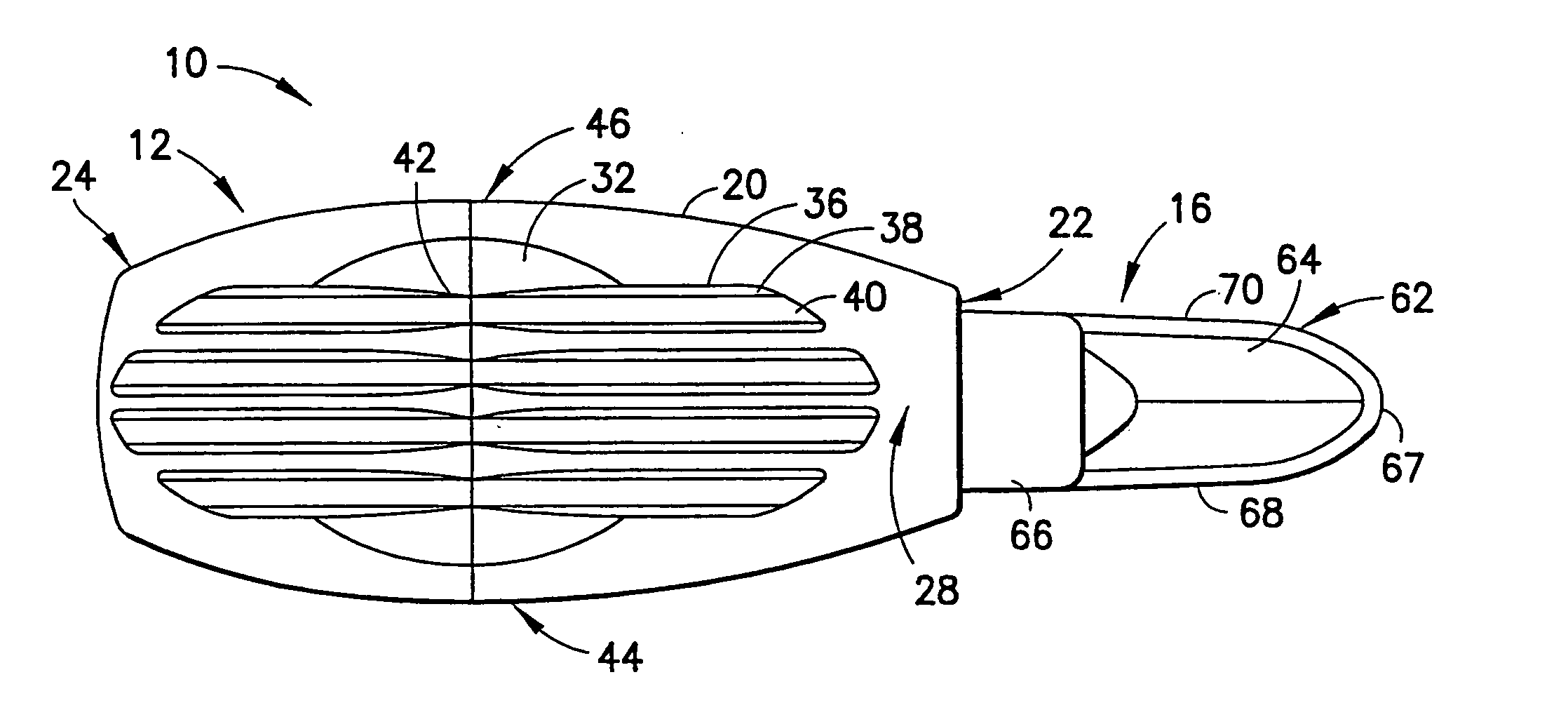
[0097] Referring further to FIGS. 7-16, a sterile tab member 16 according to one embodiment is illustrated in connection with the lancet device 10. In the tab member 16, the tab member is associated with the distal end 22 of the housing body 20 and encompasses or encloses the shield 14. In each of the embodiments of the tab member 16 to be discussed in this disclosure, the primary function of the tab member 16 is to enclose and shield the puncturing element, i.e. the lance tip, contained within the housing body 20 prior to actuating the lancet device 10. To use the lancet device, the tab member 16 must first be removed from the puncturing element. The tab member 16 is generally associated with the lancet assembly and may be integrally molded to a portion of the lancet assembly during a molding process. For example, during such a molding process, the tab member 16 may be integrally molded with the lancet structure of the lancet assembly and molded to enclose the puncturing element or...

fifth embodiment

[0109]FIGS. 32-36 show the tab member 16d. This embodiment is substantially similar to the tab member 16c discussed immediately above. In this embodiment, the paddle-shaped member 64d is also generally non-symmetrical in plan view, and the opposed edges 68d, 70d of the paddle-shaped member 64d are not oppositely curved. However, the opposed edges 68d, 70d define opposed longitudinal curved portions 88d, as shown in FIGS. 32 and 33, in a similar manner to the tab member 16c shown in FIGS. 27-31. In contrast to the immediately preceding embodiment of the tab member 16c, the opposed sides 82d, 84d of the paddle-shaped member 64d are contoured in a manner similar to the embodiment of the tab member 16b shown in FIGS. 23-36 and discussed previously. The contoured sides 82d, 84d are formed generally as finger grip indentations in a similar to the side finger grip indentations 32 in the housing body 20. The finger grip indentations formed by the contoured sides 82d, 84d are generally conca...

sixth embodiment

[0110]FIGS. 37-40 show the tab member 16e. In this embodiment, the tab member 16e has a generally cylindrical shape over its length, and only reduces in cross-section at the post portion 60e. The distal portion 62e is no longer formed with a paddle-shaped member and is also generally cylindrical-shaped over its length. In this embodiment, the distal portion 62e includes a distal gripping tip 92 formed with opposed finger grip indentations 94, 96 for grasping by the user. The finger grip indentations 94, 96 are formed similar to the side finger grip indentations 32 in the housing body 20, therefore having a hyperbolic or elliptical shape (i.e., concave) as shown in FIG. 39. The finger grip indentations 94, 96 are generally concave to naturally fit the fingertips of the user. The distal portion 62e of the tab member 16 further defines an intermediate portion or area 98 disposed between the post portion 60e and the finger grip indentations 94, 96. The intermediate portion 98 defines a ...


PUM


Abstract

A lancet device generally includes a housing having opposing lateral sides extending between a forward end and a rearward end, and a shield coaxially and movably associated with the housing. The housing includes a plurality of longitudinal ribs extending along a portion of at least one of the opposing lateral sides. The plurality of longitudinal ribs form a finger grip on at least one of, and typically both of the opposing lateral sides. The shield is generally movable from a first position in which the shield extends outwardly from the forward end of the housing to a second position in which the shield is at least partially moved within the housing, based on axial pressure applied by the user against the finger grip formed by the longitudinal ribs.

Description

[0001] The present application claims priority to U.S. Application No. 60 / 631,846 filed Nov. 30, 2004, U.S. Application No. 60 / 631,795 filed Nov. 30, 2004, and U.S. application Ser. No. 11 / 123,849 filed May 6, 2005.BACKGROUND OF THE INVENTION [0002] 1. Field of the Invention [0003] The present invention relates generally to medical puncturing devices, commonly referred to as lancets, which are used to take blood samples from patients and, more specifically, to a lancet device that is ergonomically designed for ease of use and manipulation by a user. [0004] 2. Description of Related Art [0005] Lancet devices are used in the medical field for puncturing the skin of a patient to obtain a capillary blood sample from the patient. Certain diseases, such as diabetes, require that the patient's blood be tested on a regular basis to monitor, for example, the patient's blood sugar levels. Additionally, test kits, such as cholesterol test kits, often require a blood sample for analysis. The bl...

Claims


Application Information

Patent Timeline
Patent Type & Authority Applications(United States)
IPC IPC(8): A61B17/32
CPCA61B5/1411A61B2017/00424A61B5/15142A61B5/150022A61B5/150259A61B5/150412A61B5/150503A61B5/150549A61B5/150618A61B5/150717A61B5/150824A61B5/15111A61B5/15117A61B5/1513A61B5/15144
Inventor WILKINSON, BRADLEY
Owner BECTON DICKINSON & CO
Why Eureka
Try Eureka