Processes for using a memory storage device in conjunction with tooling

a memory storage device and tooling technology, applied in the field of industrial tooling, can solve the problems of difficult to track and monitor the use of a particular tooling item, tools are often predictable, and not always predictable, so as to reduce costs, reduce overhead, and reduce the effect of taxes

Inactive Publication Date: 2006-06-15
XEROX CORP
View PDF21 Cites 18 Cited by
  • Summary
  • Abstract
  • Description
  • Claims
  • Application Information

AI Technical Summary

Benefits of technology

[0005] Even when tooling is owned and maintained in one location, it is often difficult to track and monitor usage of a particular item of tooling. For instance, a manufacturing operation may have many identical tools, and the actual usage and operating conditions experienced by one particular tool may be difficult to track among the many similar or identical tools. These and similar tracking problems become greatly exacerbated for a tool owner when the tool is used and operated by a party other than the tool owner. Use by third parties is particularly common in contract manufacturing, where a customer of a manufacturing shop often owns tools that are unique to itself. Whether such tools are designed by the customer or by the manufacturing shop, customers generally prefer to own their tooling for cost, tax, and control reasons. Ownership lowers cost since the manufacturing shop need not carry the tool on its books and charge overhead. Ownership lowers taxes by enabling the owner to take depreciation. Ownership is believed to improve control since if a customer owns an asset, the customer reasonably believes that it can direct the vendor to only use the tool for the customer.

Problems solved by technology

Such tools also are often, though not always, of predictable life before normal wear and tear require maintenance, repair, or replacement.
A general problem with tooling is tracking the location and usage of such tooling in order that proper schedules for inspection, maintenance, repair or replacement can be maintained.
In addition to scheduled maintenance, some tools wear differently depending upon their specific use or the specific operating conditions to which they are subjected.
Even when tooling is owned and maintained in one location, it is often difficult to track and monitor usage of a particular item of tooling.
For instance, a manufacturing operation may have many identical tools, and the actual usage and operating conditions experienced by one particular tool may be difficult to track among the many similar or identical tools.
These and similar tracking problems become greatly exacerbated for a tool owner when the tool is used and operated by a party other than the tool owner.
As described above, scheduling maintenance of tooling is sometimes a difficult task even when the subject tooling remains in the possession of an owner operator.
Where the tooling is in the control of a third party such as a contract manufacturer, the parties may agree by contract or otherwise how the tooling will be used and maintained, yet tracking whether such agreements are in fact followed is often difficult or impossible.
Many industrial customers have experienced much higher tool replacement expense than expected, and the industrial customer is forced to accept such replacement costs without knowing whether the tooling was maintained properly or even whether it was used in an unauthorized fashion for a customer other than the tool owner.
Understanding the causes of tooling failure or excessive wear are often difficult to determine after-the-fact since tool failure and wear can have many causes in addition to poor maintenance or excessive usage.
Such additional reasons for tool failure or wear include, without limitation, poor tool design and materials, unexpected operating conditions, etc.
Since much industrial tooling is very expensive, unexpected replacement costs can add greatly to a customers cost base over expected amounts.

Method used


Image

  • Processes for using a memory storage device in conjunction with tooling
  • Processes for using a memory storage device in conjunction with tooling
  • Processes for using a memory storage device in conjunction with tooling

Examples


Embodiment Construction

[0011] For a general understanding of the present invention, reference is made to the drawings. In the drawings, like reference numerals have been used throughout to designate identical elements.

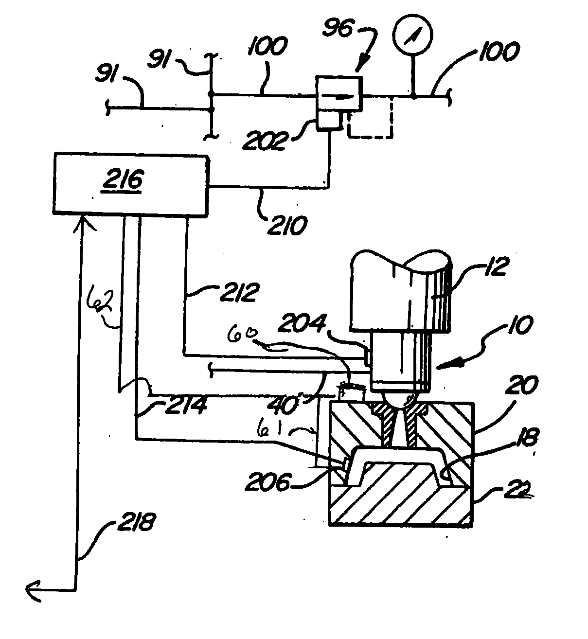
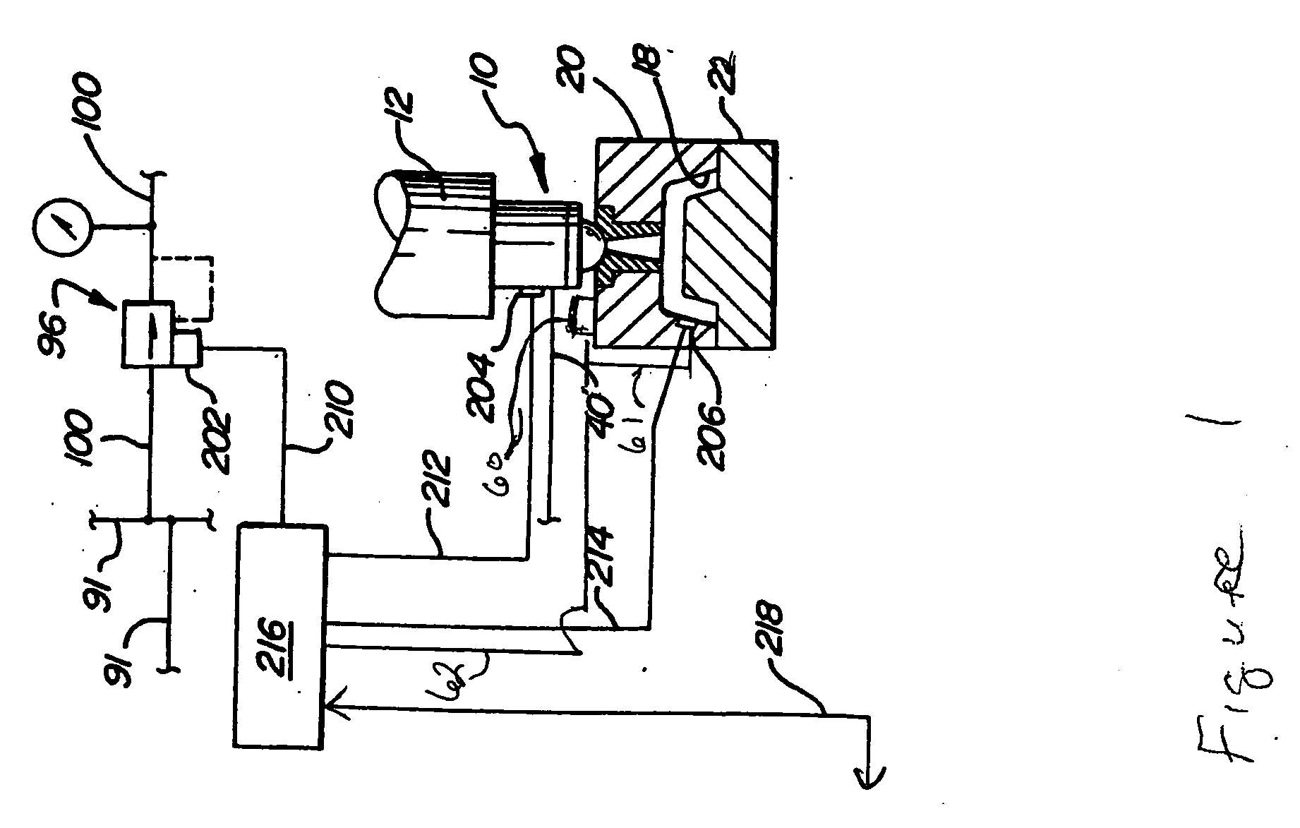
[0012] An exemplary tool with which the advantages of the present invention will be described is an injection mold. For purposes of describing typical injection mold apparatus and procedures, U.S. Pat. No. 5,118,455, issued to Loren, is hereby incorporated in its entirety herein. FIG. 1 is adapted from FIG. 1B of the '455 patent. Injection mold 50 is comprised of mold halves 20 and 22. Mold 50 and its components comprise the tooling that is subject to wear and tear during usage. Cavity 18 defines the shape of the part to be formed. Nozzle 10 receives injection resin from injection molding machine 12. The injection molding is gas assisted by gas injected through gas injection conduit 40. Conduit 40 is connected (connection not shown) to nitrogen gas supply members 91 and 100. Gas pressure is...


PUM

PropertyMeasurementUnit
radio frequenciesaaaaaaaaaa
cycle time parameteraaaaaaaaaa
durableaaaaaaaaaa

Abstract

A process for using a data memory device in conjunction with an item of tooling such as an injection mold wherein the tooling is fixedly coupled with a memory device for storing information such as tool identification information, optimal and actual operating parameters, cycle count, and similar information useful for the tracking, use, maintenance, and repair of the tooling.

Description

BACKGROUND AND SUMMARY [0001] This application relates generally to an apparatus and method for tracking the usage and operating conditions of tooling parts in general and more particularly to industrial tooling. [0002] One characteristic of modern efficient manufacturing is the contract manufacturing by vendors of many components and subassemblies of larger systems. For most large companies, such sub-contracting lowers costs and enables vendors with specialized equipment and expertise to make the components and subassemblies more efficiently and with less overhead. Engineering and design services by vendors are also often provided in conjunction with or as a substitutes for engineering design services by the manufacturer of the larger system. [0003] In many instances, components designed for specific applications are unique and require unique tooling for their manufacture. Such unique tooling can comprise dies, stamps, molds, fixtures, jigs, patterns, specialized cutting and drilli...

Claims


Application Information

Patent Timeline
Patent Type & Authority Applications(United States)
IPC IPC(8): G06F19/00
CPCG05B19/40938G05B2219/49305B29C45/76B29C2045/1796Y02P90/02
Inventor CONNER, ERIN L.PASCUCCI, JAMES A.
Owner XEROX CORP
Why Eureka
Try Eureka