
System and method for management of recovery point objectives of business continuity/disaster recovery IT solutions

a technology for business continuity and disaster recovery, applied in the field of computer systems, can solve the problems of erroneous operation, inability to integrate with all three components of conventional business continuity or disaster recovery solutions based on rpo measurement, and inability to provide real-time rpo measuremen

Inactive Publication Date: 2006-06-15
IBM GLOBAL SERVICES PTE LTD
View PDF10 Cites 98 Cited by
  • Summary
  • Abstract
  • Description
  • Claims
  • Application Information

AI Technical Summary

Benefits of technology

[0010] It is another objective of the present invention to provide systems and methods that manage the enterprise IT business continuity or disaster recovery solutions such that the desired RPO value is achieved.
[0012] It is still another objective of the present invention to provide systems and methods for managing the RPO of enterprise IT business continuity or disaster recovery solutions that enable a user to input or configure a desired RPO value for the business continuity or disaster recovery solution.

Problems solved by technology

In other words, when a disaster or an outage renders an IT business continuity solution unavailable, RPO is the data loss in time units that the IT enterprise can accept without adverse impact.
Therefore, the challenge faced by most enterprises lies in identifying the criticality of their IT enterprise application data and impact of loss of the same.
Conventional business continuity or disaster recovery solutions based on an RPO measure may not integrate with all the three components.
Some of the currently available business continuity or disaster recovery solutions work with a static value of RPO and do not provide for a real time measurement of RPO based on real time inputs obtained from all the three components.
Such dependence on manual intervention may lead to erroneous operation of the solution and added costs for the business enterprise that implements the solution.

Method used


Image

  • System and method for management of recovery point objectives of business continuity/disaster recovery IT solutions
  • System and method for management of recovery point objectives of business continuity/disaster recovery IT solutions
  • System and method for management of recovery point objectives of business continuity/disaster recovery IT solutions

Examples


Embodiment Construction

[0041] The present invention would now be discussed in context of embodiments as illustrated in the accompanying drawings.

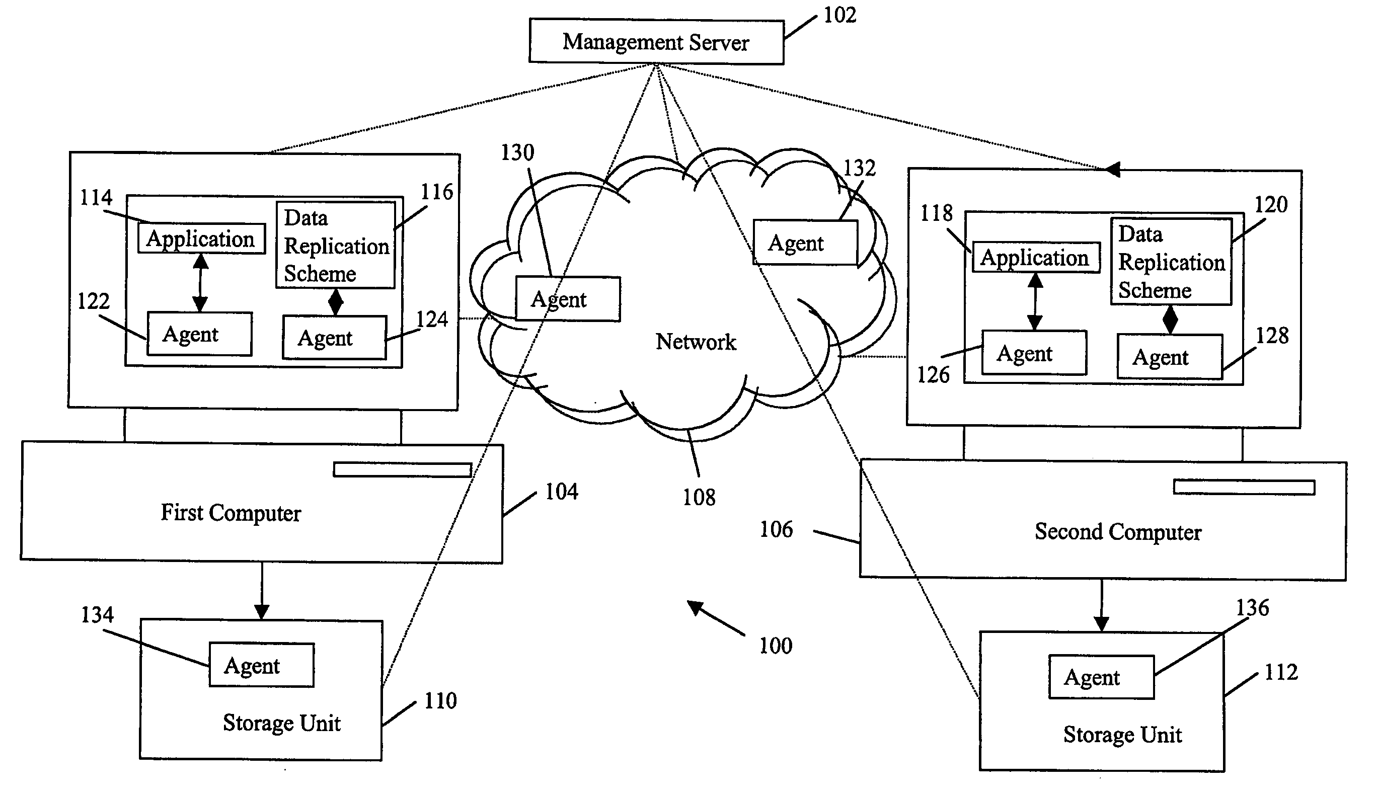
[0042]FIG. 1 illustrates an exemplary environment in which the system for management of recovery point objectives (RPO) for maintaining business continuity of an Information Technology (IT) enterprise operates, in accordance with an embodiment of the present invention. System 100 comprises a management server 102, a first computer 104, a second computer 106, a network 108 connecting the first computer 104 and the second computer 106, a first storage unit 110 connected to the first computer 104, and a second storage unit 112 connected to the second computer 106. An application 114 of the IT enterprise that is required to be available continuously runs on the first computer 104. A data protection scheme 116 is configured to protect the application 114. An instance 118 of the application 114 runs on the second computer 106. An instance 120 of the data protection sc...


PUM


Abstract

The present invention provides a system and method for management of Recovery Point Objectives (RPO) of a business continuity or disaster recovery solution. The system comprises a management server logically coupled with at least a first computer, at least a second computer, and a network coupling the first and the second computers. The first and second computers host at least one continuously available application and at least one data protection scheme for replicating the application data; the application data being periodically replicated from the first computer to at least the second computer. The system manages RPO by inputting an RPO value for the solution, calculating a real time RPO value for the solution, and making the real time RPO value equal to the input RPO value.

Description

FIELD OF INVENTION [0001] The present invention relates generally to computer systems. More particularly, the present invention relates to monitoring, measurement and management of Recovery Point Objectives (RPO) of enterprise IT business continuity or disaster recovery solutions. BACKGROUND OF THE INVENTION [0002] In the increasingly competitive times of today, implementing systems and methods for maintaining business continuity is no longer an optional requirement for business enterprises, especially for enterprises that use or are fully or partially dependent on Information Technology (IT). Such enterprises can be broadly termed as IT enterprises. Since the efficient working of most of such IT enterprises depends on their business continuity or disaster recovery management infrastructure, implementing a sound enterprise IT business continuity or disaster recovery solution has almost become a mandatory requirement. Costs incurred during business downtime are usually significant, t...

Claims


Application Information

Patent Timeline
IPC IPC(8): G06F17/30
CPCG06F17/30008G06F16/2308G06F11/1464
Inventor PULAMARASETTI, CHANDRASEKHARMULPURI, RAJASEKHARNARAYANASWAMY, LAKSHMANRAGHUNATHAN, RAVI KUMARNIMISHAKAVI, KRISHNAVONNA, RAJASEKHAR
Owner IBM GLOBAL SERVICES PTE LTD
Learn More