Storage system condition indicator and method

a storage system and condition indicator technology, applied in the field of digital data storage systems and methods, can solve the problems of disc-surface corruption on an infrequently used area of the disk array, design may not be able to use any capacity on the drive that exceeds the capacity of the smallest drive in the array, and it is not always possible to determine that corruption has occurred, so as to achieve a good level of data safety

Active Publication Date: 2006-06-15
STORCENTRIC DIP LENDER LLC
View PDF98 Cites 61 Cited by
  • Summary
  • Abstract
  • Description
  • Claims
  • Application Information

AI Technical Summary

Problems solved by technology

Typically disk arrays using a RAID pattern are complex structures that require management by experienced information technologists.
Moreover in many array designs using a RAID pattern, if the disk drives in the array are of non-uniform capacities, the design may be unable to use any capacity on the drive that exceeds the capacity of the smallest drive in the array.
One problem with a standard RAID system is that it is possible for disc-surface corruption to occur on an infrequently used area of the disk array.
In the event that another drive fails, it is not always possible to determine that corruption has occurred.
Maintenance of a hot spare disk is generally complex, and so is generally handled by a skilled administrator.
A hot spare disk also represents an added expense.

Method used


Image

  • Storage system condition indicator and method
  • Storage system condition indicator and method
  • Storage system condition indicator and method

Examples


Embodiment Construction

[0042] Definitions. As used in this description and the accompanying claims, the following terms shall have the meanings indicated, unless the context otherwise requires:

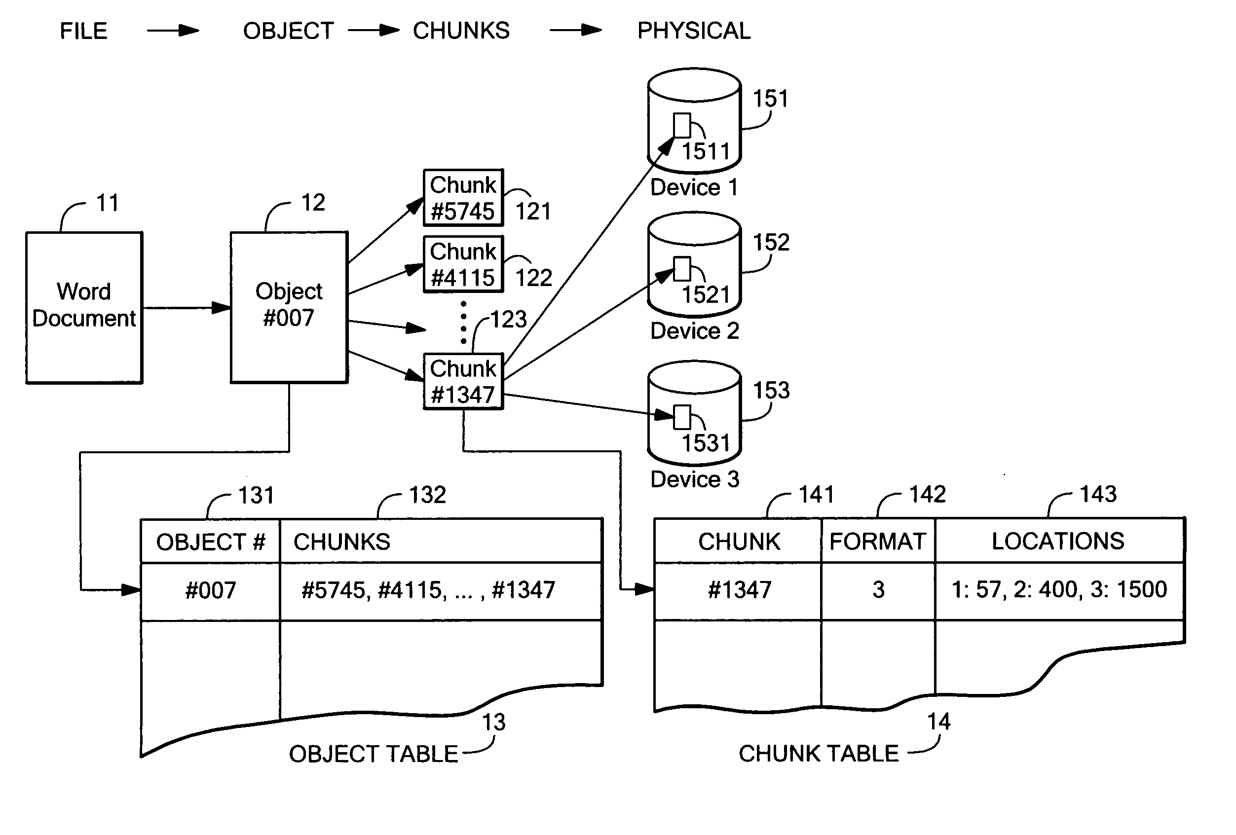
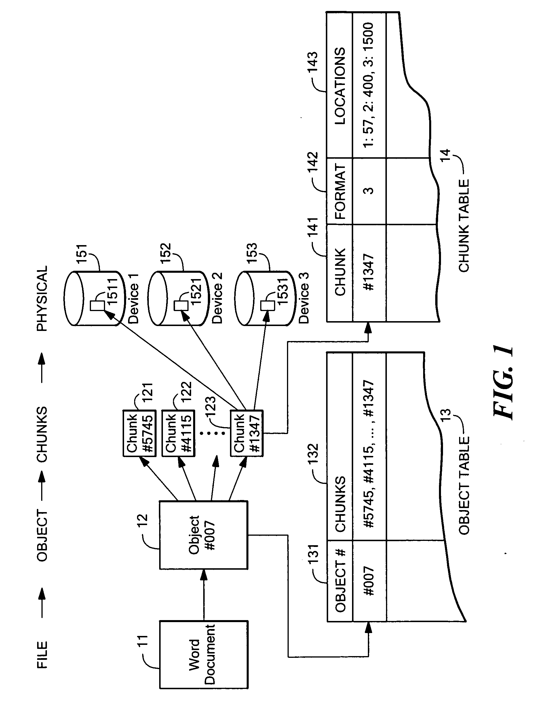
[0043] A “chunk” of an object is an abstract slice of an object, made independently of any physical storage being used, and is typically a fixed number of contiguous bytes of the object.

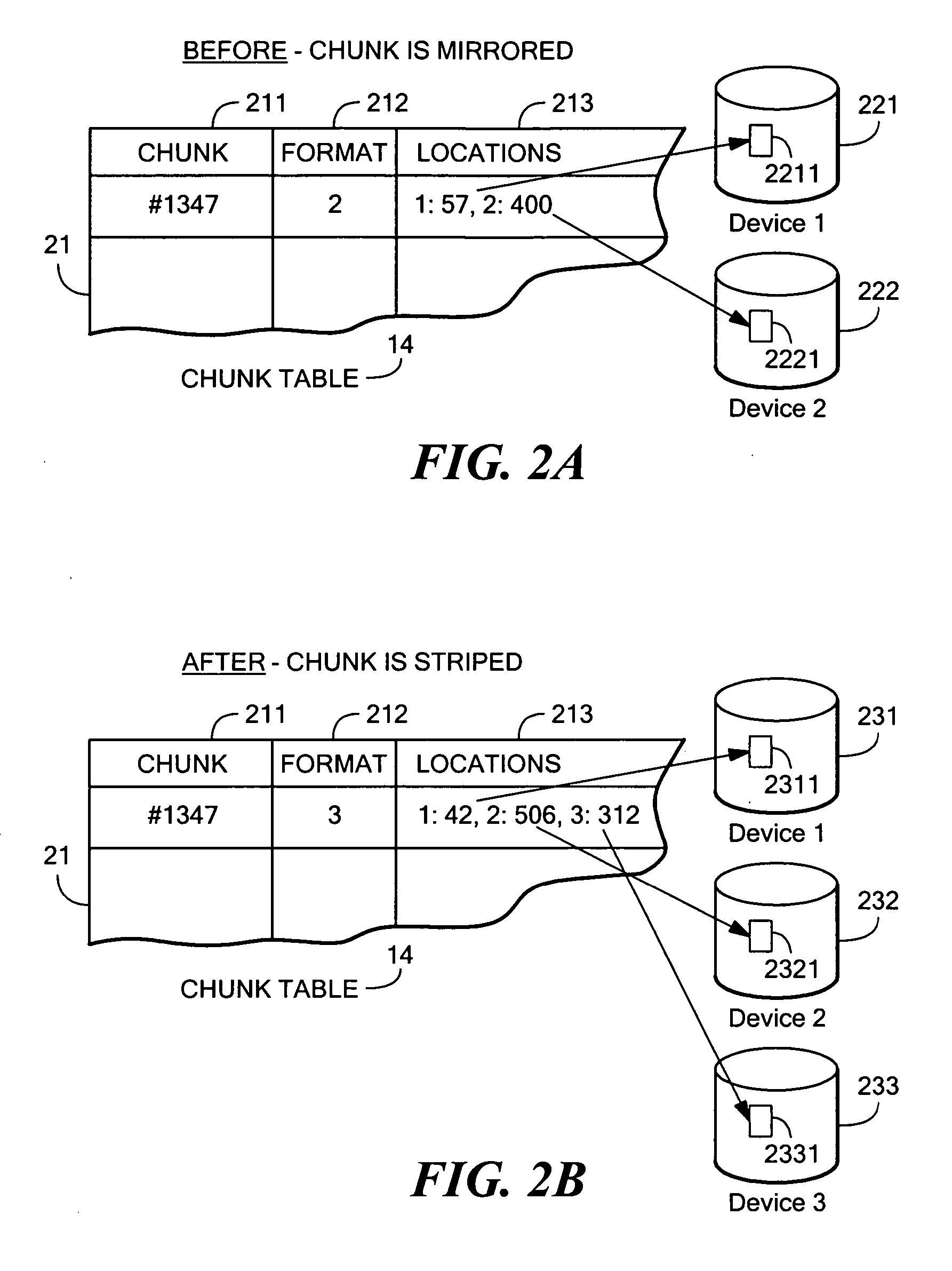
[0044] A fault-tolerant “pattern” for data storage is the particular which by data is distributed redundantly over one or more storage devices, and may be, among other things, mirroring (e.g., in a manner analogous to RAID1), striping (e.g., in a manner analogous to RAID5), RAID6, dual parity, diagonal Parity, Low Density Parity Check codes, turbo codes, or other redundancy scheme or combination of redundancy schemes.

[0045] A hash number for a given chunk is “unique” when the given chunk produces a hash number that generally will differ from the hash number for any other chunk, except when the other chunk has data content identica...


PUM


Abstract

A storage system condition indicator and method provides a visual display representing the operating condition of a set of storage devices. Various operating conditions may be defined based on available storage capacity and capacity to store data redundantly. One or more indicators may be used to represent the operating condition of the set of storage devices. The indicator(s) may be used to indicate whether additional storage capacity is recommended and, in a storage array, which slot in the array should be updated with additional storage capacity.

Description

PRIORITY [0001] This application claims priority from the following United States Provisional Patent Applications, which are hereby incorporated herein by reference in their entireties: [0002] 60 / 625,495 filed on Nov. 5, 2004; and [0003] 60 / 718,768 filed on Sep. 20, 2005.TECHNICAL FIELD AND BACKGROUND ART [0004] The present invention relates to digital data storage systems and methods, and more particularly to those providing fault-tolerant storage. [0005] It is known in the prior art to provide redundant disk storage in a pattern according to any one of various RAID (Redundant Array of Independent Disks) protocols. Typically disk arrays using a RAID pattern are complex structures that require management by experienced information technologists. Moreover in many array designs using a RAID pattern, if the disk drives in the array are of non-uniform capacities, the design may be unable to use any capacity on the drive that exceeds the capacity of the smallest drive in the array. [0006...

Claims


Application Information

Patent Timeline
Patent Type & Authority Applications(United States)
IPC IPC(8): G06F11/00
CPCG06F3/0607G11B2220/65G06F3/0689G06F11/1084G06F11/1096G06F11/1658G06F11/1662G06F11/2069G06F11/2087G06F11/2094G06F11/325G06F2211/1004G06F2211/1023G06F2211/1028G11B27/11G11B27/329G11B2220/415G06F3/0644G06F3/06G06F11/10G06F12/16
Inventor BARRALL, GEOFFREY S.
Owner STORCENTRIC DIP LENDER LLC
Why Eureka
Try Eureka