System for producing electric power from renewable sources and a control method thereof

a technology of renewable sources and electric power, applied in the direction of dc source parallel operation, circuit arrangement, transportation and packaging, etc., can solve the problems of real dc/ac converters not being able to guarantee, oscillation of points, and consequent degradation of mppt efficiency, so as to reduce the drawback and maintain the preferential point of operation.

Inactive Publication Date: 2011-05-31
MARICI HLDG THE NETHERLANDS BV
View PDF3 Cites 183 Cited by
  • Summary
  • Abstract
  • Description
  • Claims
  • Application Information

AI Technical Summary

Benefits of technology

[0025]The object of the present invention is to provide a device and a control method that will enable a substantial reduction of this drawback by optimizing the delivery of power from a system for producing electric power from renewable sources, especially photovoltaic panels, or more in general by optimizing the control of the source, via a more accurate maintenance of the preferential point of operation.
[0031]The corrector block basically constitutes a regulator which, by acting on the control parameter for the boost converter, maintains the source in the proximity of the preferential point of operation. The corrector block is designed to suppress or reduce the effect on the reference signal of at least one disturbance at a pre-determined frequency, coming from the electrical network to which the output of said inverter is connected. Typically, said disturbance is an oscillation at twice the network frequency that is superimposed on a continuous value of the input voltage of the inverter (bulk voltage) and that propagates through the booster stage towards the input of the latter.

Problems solved by technology

When the power supplied by the alternative source is insufficient to supply the load, it is supplied either totally or in part by power drawn from the network.
It is known that a real DC / AC converter cannot guarantee conditions of operation characterized by a current and a voltage that are rigorously constant at the DC end and at the same time by a current that is perfectly in phase with the voltage at the AC end.
The aforesaid disturbance propagates through the DC / DC stage from the bulk capacitor to the terminals of the field of photovoltaic panels 1, causing an oscillation of the point of operation in the neighbourhood of the point of maximum power, with consequent degradation of the efficiency of the MPPT.
(2) that the reduction of the oscillation at the second harmonic on the bulk voltage at very low levels involves the use of capacitors having a very high capacitance, with consequent drawbacks in terms of cost of the device.
In any case, the reduction of the oscillation of the bulk voltage is not satisfactory.
The system works in an incorrect way in so far as it is not possible to identify the point of maximum power that can be supplied.
The consequence of this is that a converter that operates in this way is not able to extract from the field of photovoltaic panels 1 all the power that it could in actual fact deliver at every condition of insolation.
Said progressive running-down is not necessarily uniform for all the cells and represents, in this case, the non-controllable event.
In all the above situations, the block that controls the inverter so as to maintain the system in the preferential point of operation can present an even markedly reduced efficiency on account of disturbances coming from the electrical network to which the inverter is connected and on which the current generated by the source is introduced.

Method used


Image

  • System for producing electric power from renewable sources and a control method thereof
  • System for producing electric power from renewable sources and a control method thereof
  • System for producing electric power from renewable sources and a control method thereof

Examples


Embodiment Construction

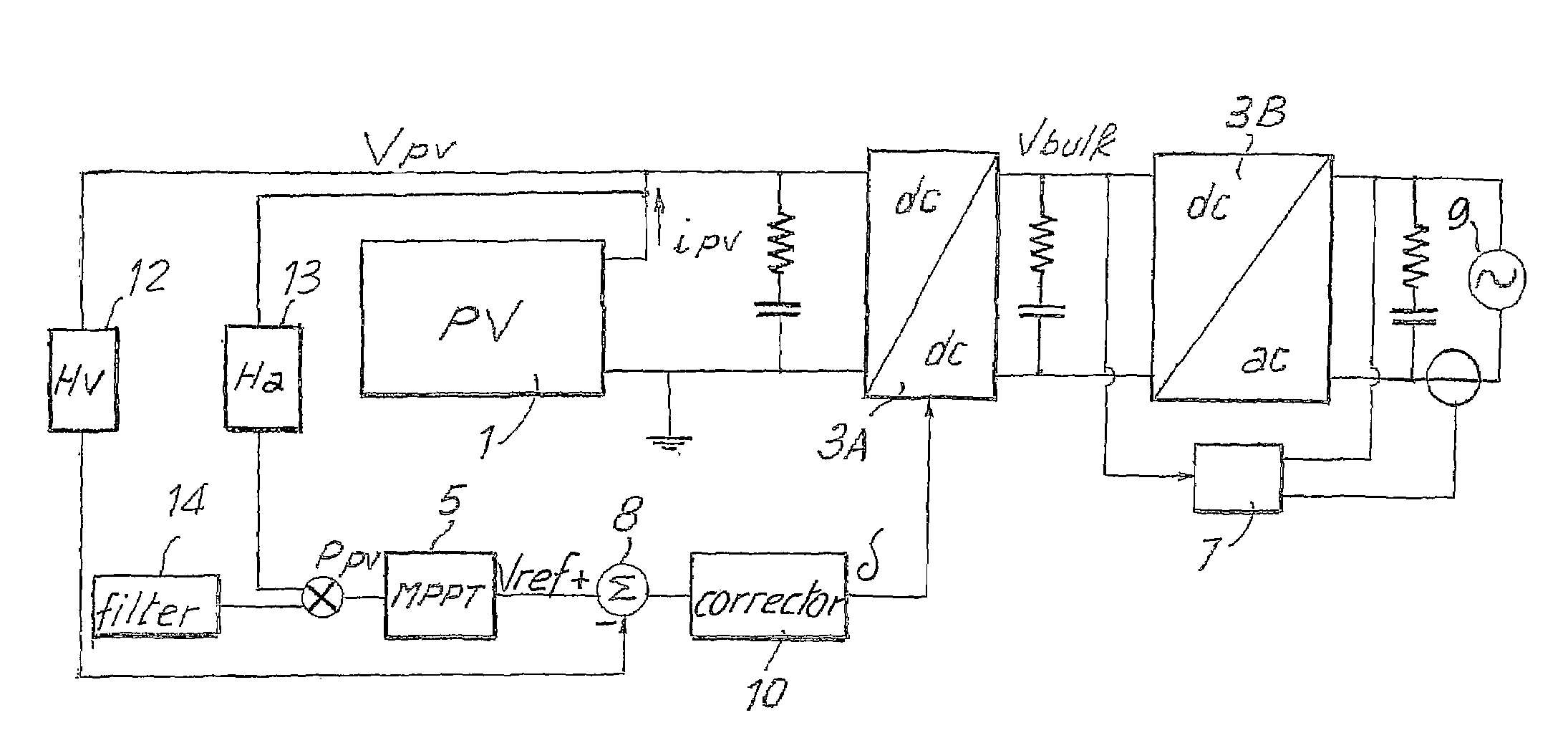
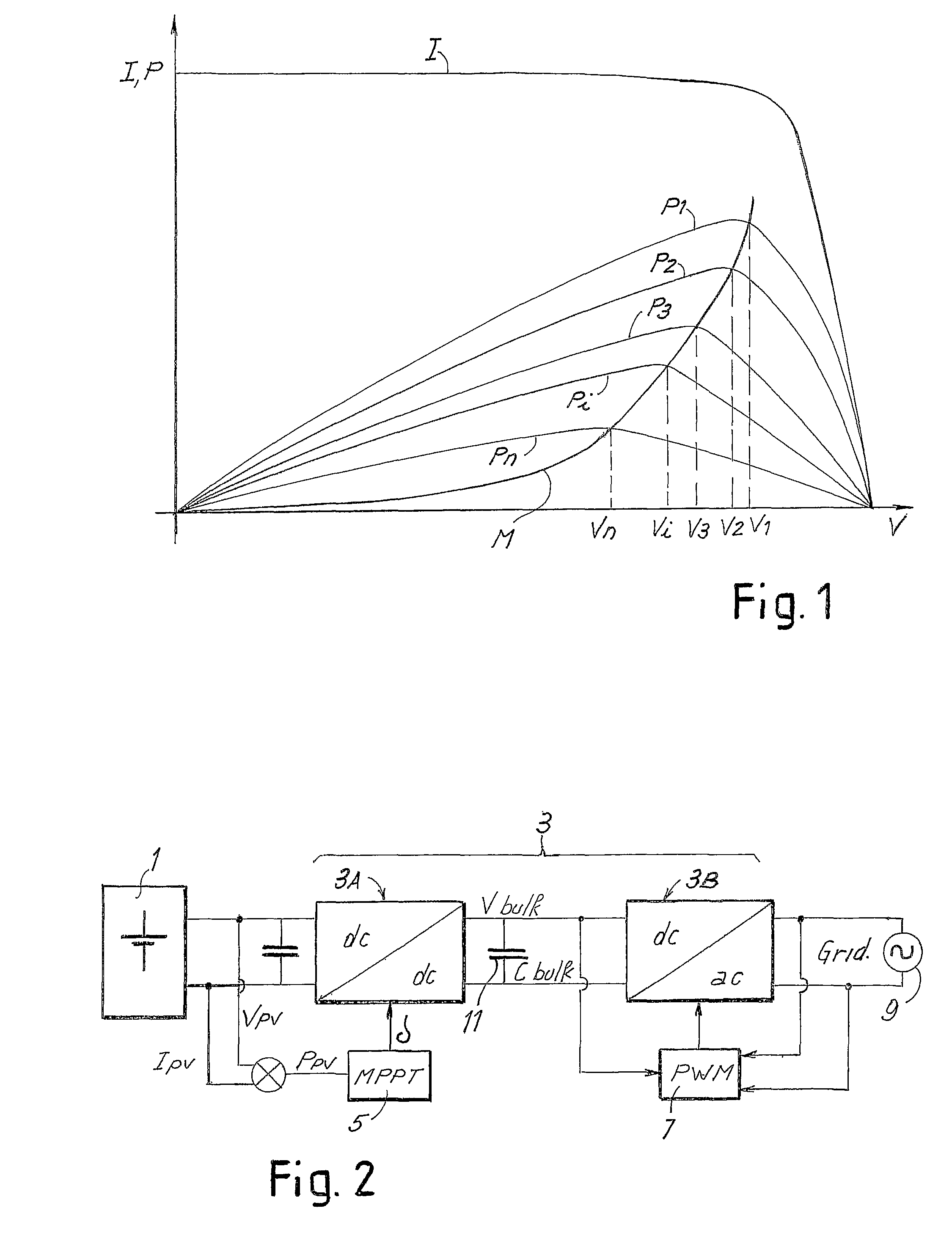
[0056]FIG. 6 shows a block diagram of a converter for photovoltaic panels modified according to the present invention. With the same notation used in FIG. 2, designated by 1 is the field of photovoltaic panels and by 3 the converter comprising an input or boosting stage 3A, and an output stage 3B of interface to the network, which is represented schematically by a voltage source 9. The stage 3A is constituted by a DC / DC converter, which sees to boosting the output voltage of the field of photovoltaic panels 1 to the programmed input bulk voltage (Vbulk) of the second stage 3B, which is constituted by a DC / AC inverter. Designated as a whole by 5 is a control block that executes an MPPT function, and designated by 7 is a block for controlling the DC / AC inverter, which maintains the current at output from the inverter in phase with the network voltage, the electrical network being schematically represented by a voltage source 9. The control block 7 comprises the output-current-phase co...


PUM


Abstract

Described herein is a system for generating electric power, comprising: an electric-power source (1) having a preferential point of operation; a double-stage inverter (3A, 3B), which transfers the energy from said source to an external a.c.-voltage electrical network (9); a block (5) for identification of the preferential point of operation, which supplies a reference signal according to the conditions of operation of the electric-power source and to the preferential point of operation of said source; a corrector block (10), provided for setting the parameter for control of the boost converter (3A) of the double-stage inverter (3A, 3B) as a function of the reference signal and of a signal of actual operation of said electric-power source, and for maintaining the source in the proximity of the preferential point of operation.

Description

TECHNICAL FIELD[0001]The present invention relates to improvements to systems for producing electric power from renewable sources, such as for example (but not exclusively) photovoltaic panels. In particular, the present invention relates to improvements to methods and devices for the control of systems for producing electric power, which have the function of maximizing the extraction of power.[0002]More in general, the present invention relates to the control of sources of electric power that have a preferential point of operation, which is correlated to a parameter that can vary as a function of a non-controllable event. In the case of photovoltaic panels, said preferential point of operation is typically represented by the point along the current-voltage curve, which supplies the maximum power that can be supplied by the field of photovoltaic panels. This preferential point of operation varies as the insolation, i.e. the solar power incident on the field of photovoltaic panels, v...

Claims


Application Information

Patent Timeline
Patent Type & Authority Patents(United States)
IPC IPC(8): H02M1/12
CPCH02M3/156H02J3/383H02J3/386H02M2001/0025Y02E10/763Y10S323/906Y02E10/563H02J2300/24H02J3/381Y02E10/56H02J3/46H02M1/0025
Inventor NOCENTINI, DANIOMACERINI, SAUROFEMIA, NICOLAVITELLI, MASSIMOSPAGNUOLO, GIOVANNIPETRONE, GIOVANNIDE ROSA, FILIPPOSIRIANNI, ANTONIO
Owner MARICI HLDG THE NETHERLANDS BV
Why Eureka
Try Eureka