
Method for rapid catalyst heating

a technology of catalyst heating and control strategy, which is applied in the direction of electric control, speed sensing governor, machines/engines, etc., can solve the problems of reducing the pumping work of those cylinders, and achieve the effects of increasing heat, increasing engine load condition, and increasing ignition timing retard

Inactive Publication Date: 2003-05-27
FORD GLOBAL TECH LLC
View PDF119 Cites 177 Cited by
  • Summary
  • Abstract
  • Description
  • Claims
  • Application Information

AI Technical Summary

Benefits of technology

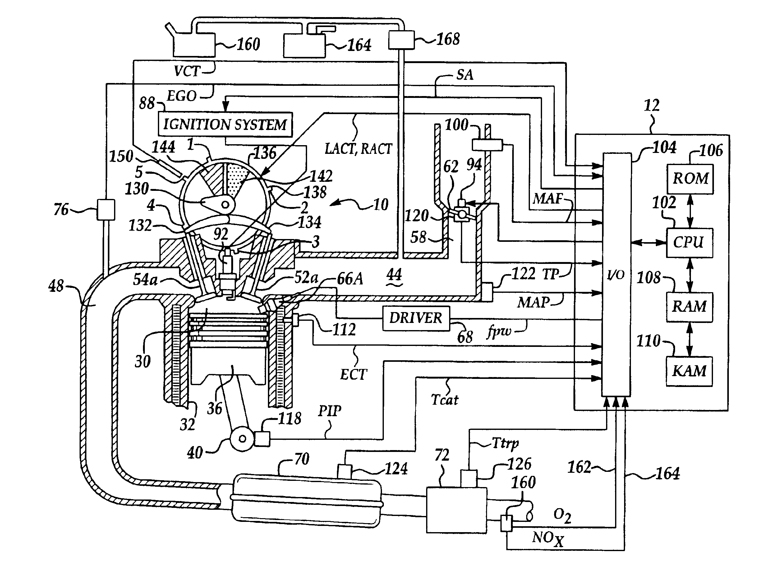
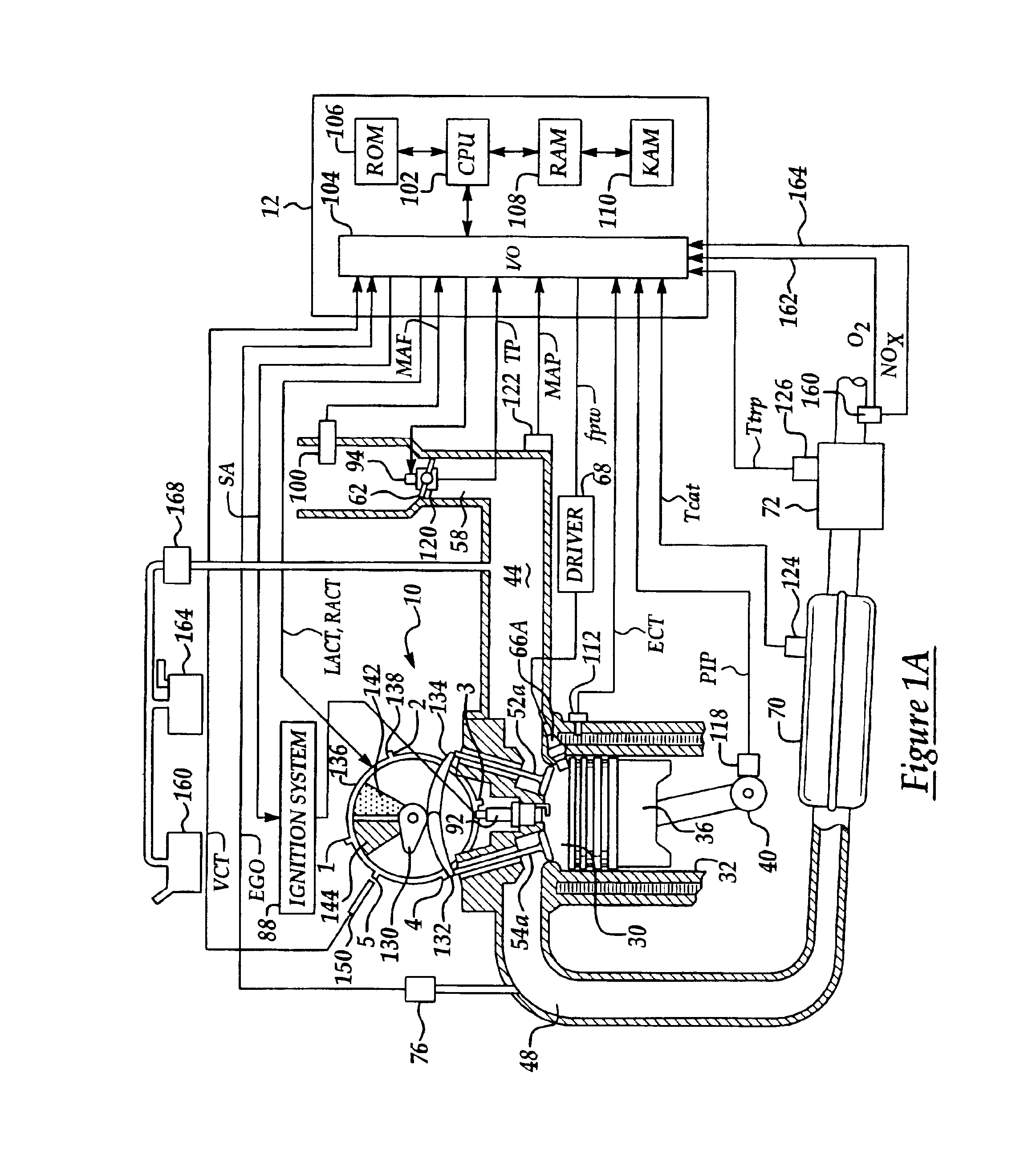
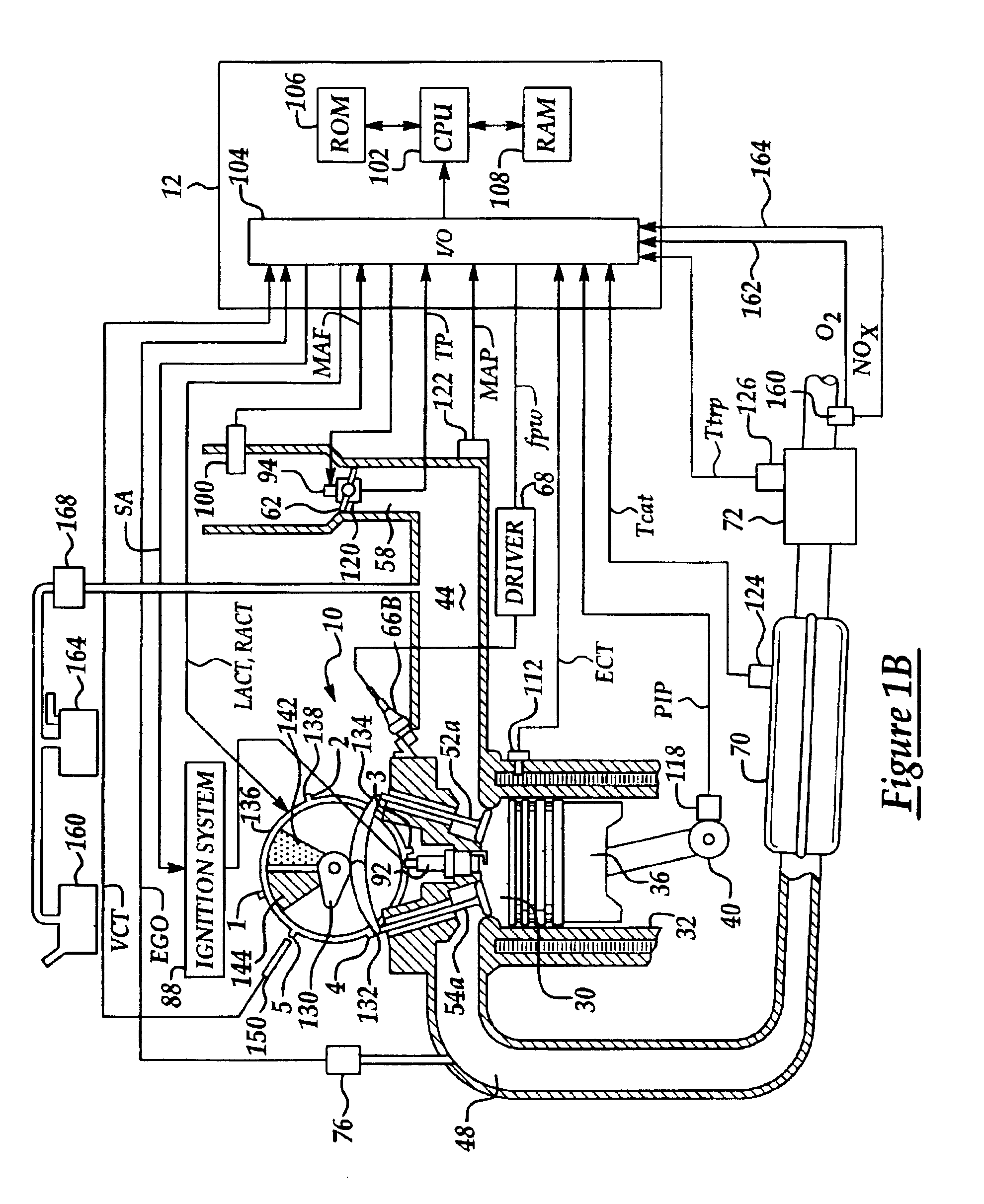
An advantage of such an approach is that it is possible to provide heat for rapidly heating an emission control device without the vibration problem caused by excessive ignition timing retard. In other words, operating an engine with some cylinders producing output and others producing substantially no output creates less vibration than operating all cylinders producing output at a retarded ignition timing.
In other words, if a large engine load is placed on the engine and adjustment of engine air flow and the first cylinder group ignition timing to the optimal ignition timing is insufficient to maintain the desired engine idle speed, then additional torque is supplied from the second cylinder group by advancing the ignition timing towards the optimal ignition timing. While this reduces the engine heat generated, it only happens for a short period of time to maintain engine idle speed, and therefore, has only a minimal effect on catalyst temperature. Thus, according to the present invention, it is possible to quickly produce a very large increase in engine output since the engine has significant amount of ignition timing retard between the first and second cylinder groups.

Problems solved by technology

As such, the cylinders combusting a rich mixture are operating at a higher load, which reduces the pumping work of those cylinders.

Method used


Image

  • Method for rapid catalyst heating
  • Method for rapid catalyst heating
  • Method for rapid catalyst heating

Examples


example 2

of FIG. 13I illustrates operation according to the present invention. In particular, the ignition timing of the second group (spk2') is substantially more retarded than the ignition timing of the first cylinder group of Example 2 (spk2). Further, the air and fuel amounts (a2, f2) are greater than the air amounts in Example 1. As a result of operation , the first cylinder group produces engine torque (T2), while the second cylinder group produces engine torque (T2). In other words, the first cylinder group produces more engine torque than when operating according to Example 1 since there is more air and fuel to combust. Also note that the first cylinder group of Example 2 has more ignition retard from optimal timing than the ignition timing of group 1 of Example 1. Also, note that the engine torque from the second cylinder group (T2') is less than the engine torque produced by the first and second cylinder group of Example 1, due to the severe ignition timing retard from optimal timi...


PUM


Abstract

A method is disclosed for controlling operation of an engine coupled to an exhaust treatment catalyst. Under predetermined conditions, the method operates an engine with a first group of cylinders combusting a lean air / fuel mixture and a second group of cylinders pumping air only (i.e., without fuel injection). In addition, the engine control method also provides the following features in combination with the above-described split air / lean mode: idle speed control, sensor diagnostics, air / fuel ratio control, adaptive learning, fuel vapor purging, catalyst temperature estimation, default operation, and exhaust gas and emission control device temperature control. In addition, the engine control method also changes to combusting in all cylinders under preselected operating conditions such as fuel vapor purging, manifold vacuum control, and purging of stored oxidants in an emission control device.

Description

BACKGROUND OF INVENTION1. Field of the InventionThe present invention relates to control strategies for engines, and more particularly, to control strategies for rapidly heating an emission control device.2. Background of the InventionEmission control devices, such as catalytic converters, can reduce emissions generated by engine combustion. However, the effectiveness of such emission control devices varies with operating temperature. For example, the efficiency of an emission control device may be much greater at higher temperatures than it is at lower temperature. Typically, a "light-off" temperature is used to signify a certain temperature above which a prescribed efficiency is achieved.In vehicle emission control systems, measures are taken to rapidly heat emission control devices after starting of a vehicle, so that tail pipe emissions can be minimized. In particular, as described in U.S. Pat. No. 5,479,745, an ignition timing signal is retarded during cold engine operation to ...

Claims


Application Information

Patent Timeline
IPC IPC(8): F02D41/02F02D41/36F02D41/34F02D41/32F02D35/00F02D31/00F02D41/00
CPCF02D41/0245F02D41/0087F02D31/002F02D31/003F02D41/003F02D41/0082Y02T10/26F02D2200/0804F02D2250/18F02P5/1506F02P5/1512Y02T10/12Y02T10/40
Inventor SURNILLA, GOPICHANDRA
Owner FORD GLOBAL TECH LLC
Learn More