Industrial robot

a robot and industrial technology, applied in the field of industrial robots, can solve the problems of extreme difficulty or inability to simultaneously satisfy such strict conditions, and achieve the effects of wide operation range, high mechanical rigidity, and high load condition

Active Publication Date: 2019-01-29
KAWASAKI HEAVY IND LTD
View PDF33 Cites 0 Cited by
  • Summary
  • Abstract
  • Description
  • Claims
  • Application Information

AI Technical Summary

Benefits of technology

[0027]According to the present invention, an industrial robot capable of ensuring high mechanical rigidity, servo rigidity, and precision under a high load condition over a wide operation range can be provided.

Problems solved by technology

Now, in some uses, high mechanical rigidity, servo rigidity, and precision need to be ensured under a high load condition over a wide operation range, while it is extremely difficult or impossible to simultaneously satisfy such strict conditions by the above-mentioned conventionally proposed robot.

Method used


Image

  • Industrial robot
  • Industrial robot
  • Industrial robot

Examples


Embodiment Construction

[0041]Hereunder, an industrial robot according to one embodiment of the present invention will be described referring to the drawings.

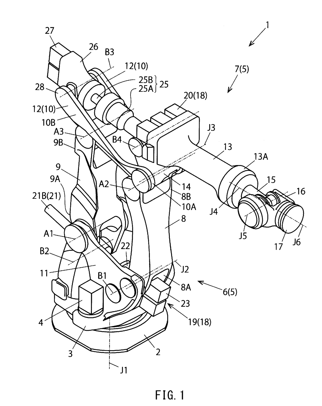
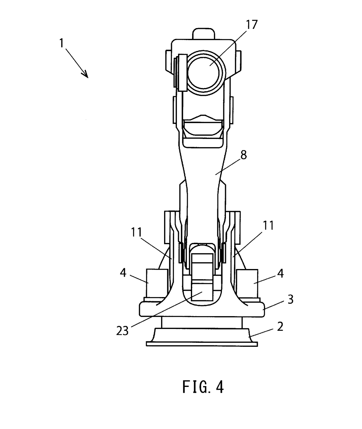
[0042]As illustrated in FIG. 1 to FIG. 7, an industrial robot 1 according to this embodiment has a base 2 which is installed on a floor surface, and a turning base portion 3 is provided to this base 2 so as to be rotatable about a first rotational axis (turning axis) J1 extending in a vertical direction.

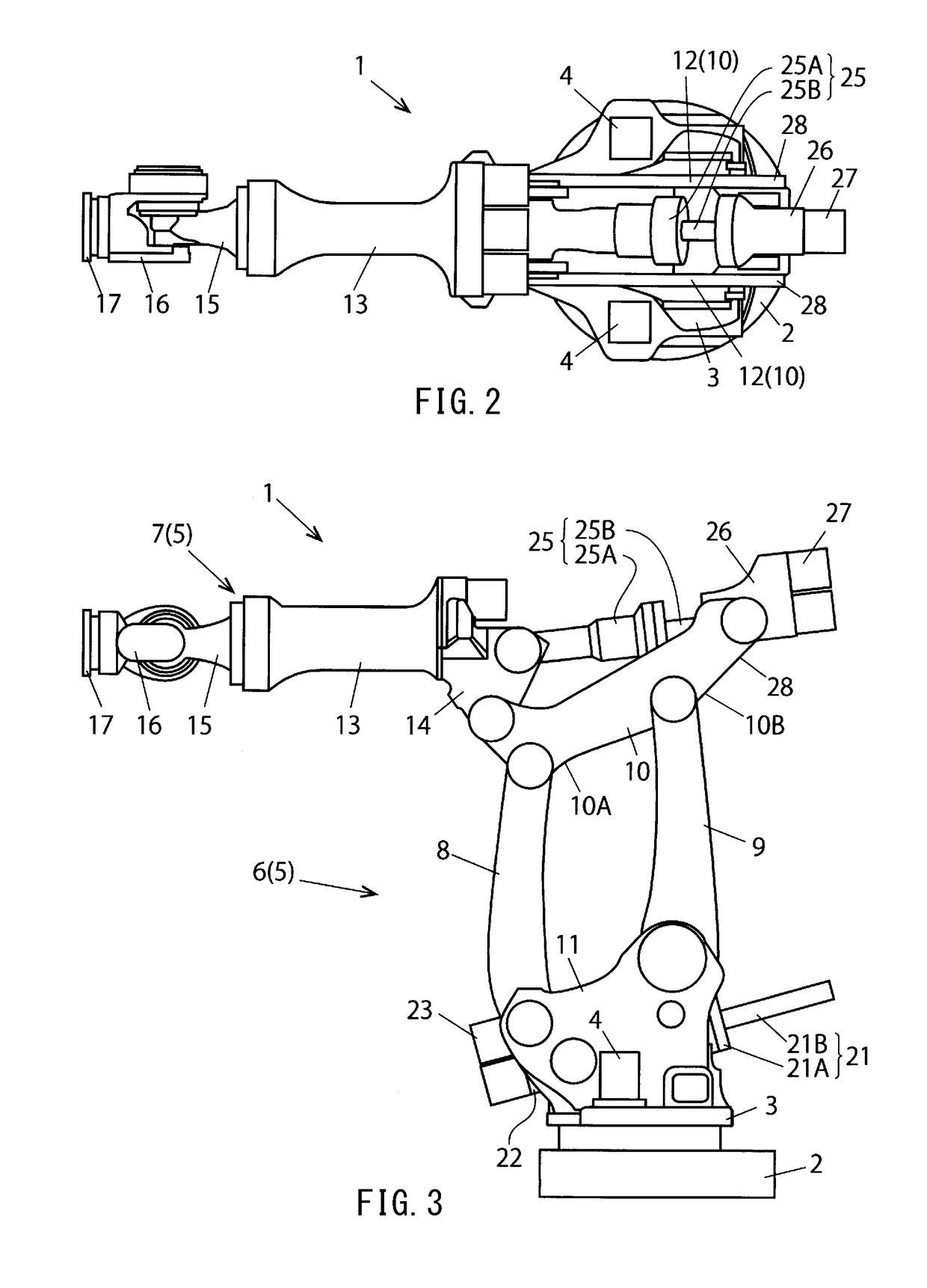
[0043]As is well illustrated in FIG. 2, a pair of servo motors 4 are provided on both left and right sides of the turning base portion 3, and the turning base portion 3 is rotatively driven about the first rotational axis with respect to the base 2 by these servo motors 4.

[0044]As is well illustrated in FIG. 1, an arm unit 5 is provided to the turning base portion 3 of the robot 1, and the arm unit 5 has a lower arm mechanism 6 having a parallel link structure and an upper arm mechanism 7 provided to a top of the lower arm mechanism 6.

[0045]As is well ...


PUM


Abstract

An arm unit of a robot has a lower arm mechanism including a parallel link structure and an upper arm mechanism. The lower arm mechanism has a front link and a rear link including respective lower ends rotatably connected to the base portion. A lower arm drive mechanism has a lower ball screw and a lower bearing portion supporting a shaft so as to be rotatable about its axis. An extending portion extending from the lower end of the rear link is connected to a nut so as to be rotatable about a nut side rotational axis. The lower bearing portion is connected to a base portion so as to be rotatable about a bearing portion side rotational axis. Thus, high mechanical rigidity can be ensured over a wide operation range under a high load condition.

Description

TECHNICAL FIELD[0001]The present invention relates to an industrial robot, particularly an industrial robot comprising an arm mechanism configured by a plurality of links.BACKGROUND ART[0002]Conventionally, the industrial robot is installed in various production factories of electric apparatus, machines, automobiles, and the like, as a conveyance robot for conveying objects and a work robot for machining objects.[0003]The industrial robot takes on various forms according to its use, and it needs high mechanical rigidity and high servo rigidity to be operated under a high load condition without difficulty. Further, the robot needs to be operated over a wide range in some uses.[0004]In order to ensure high mechanical rigidity of the robot, a robot is proposed wherein a parallel link structure is employed in each of an upper arm mechanism and a lower arm mechanism (Patent Document 1).[0005]Further, another robot is proposed wherein the parallel link structure is employed in the lower a...

Claims


Application Information

Patent Timeline
Patent Type & Authority Patents(United States)
IPC IPC(8): B25J9/06B25J9/10B25J9/12
CPCB25J9/06B25J9/12B25J9/1065Y10S901/23B25J9/106B25J9/042B25J9/108B25J9/126
Inventor KITAMURA, SHINJIYAMAMOTO, MASATOYOSHINO, KOJI
Owner KAWASAKI HEAVY IND LTD
Why Eureka
Try Eureka