Fixed-type constant velocity universal joint

a constant velocity, universal joint technology, applied in the direction of clutches, mechanical devices, couplings, etc., can solve the problem of uneconomical to achieve the roughness of the finished surface of ra 0.15 m or less, and achieve the effect of strengthening the cage, enhancing the durability, and enhancing the durability

Inactive Publication Date: 2014-07-08
NTN CORP
View PDF21 Cites 0 Cited by
  • Summary
  • Abstract
  • Description
  • Claims
  • Application Information

AI Technical Summary

Benefits of technology

[0014]In view of such circumstances, the present invention has been made to provide a fixed type constant velocity universal joint which can achieve, at low cost, excellent properties in terms of the durability, the high load condition, the low load condition, and the high angle condition.

Problems solved by technology

However, owing to shapes which occupy large surface areas, and are intermittent and complicated, it is uneconomical to achieve finished surface roughnesses of Ra 0.15 μm or less.

Method used


Image

  • Fixed-type constant velocity universal joint
  • Fixed-type constant velocity universal joint
  • Fixed-type constant velocity universal joint

Examples


Embodiment Construction

[0040]In the following, description is made of embodiments of the present invention with reference to the drawings.

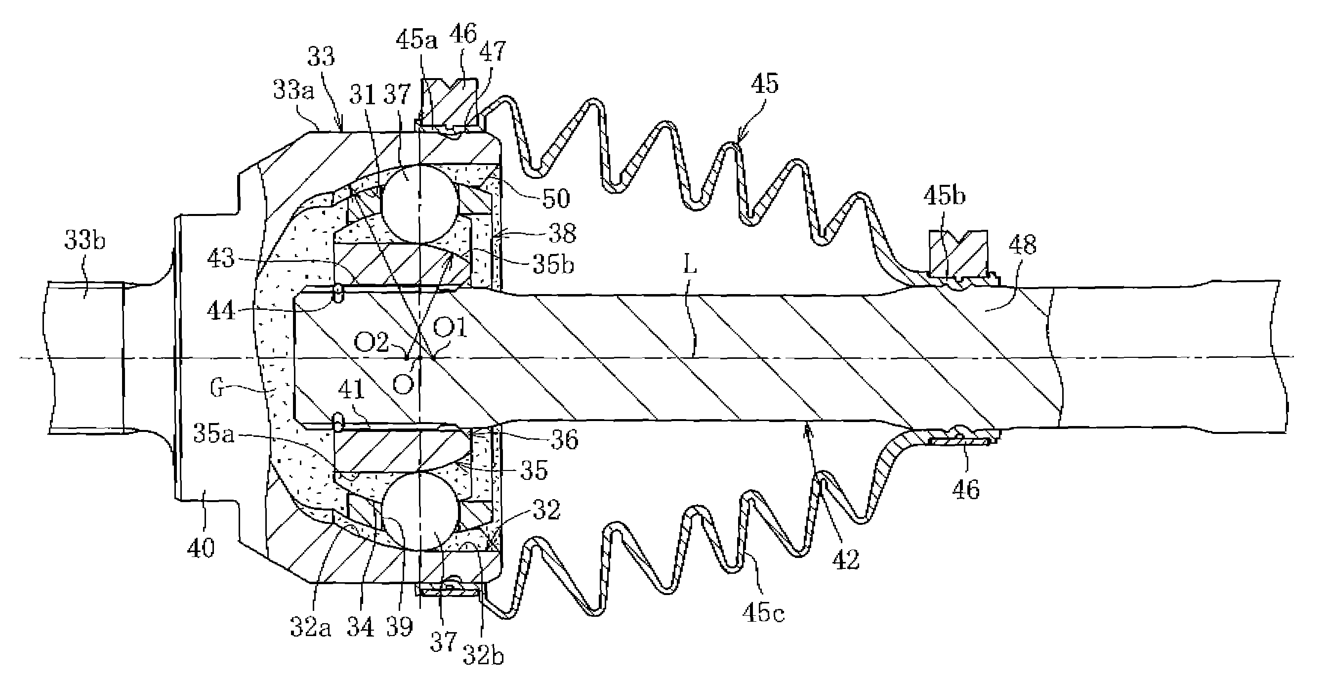
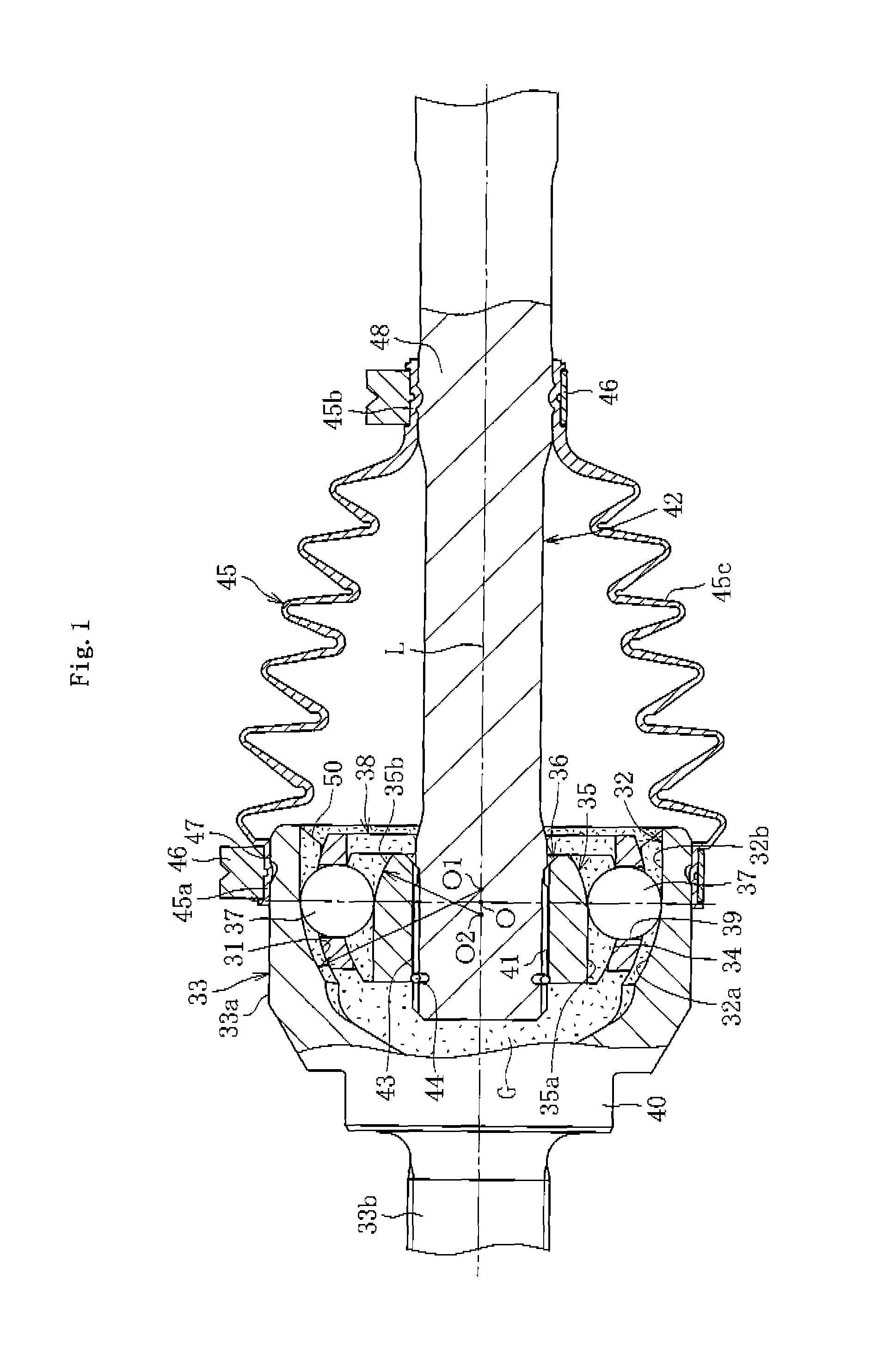
[0041]FIG. 1 illustrates a fixed type constant velocity universal joint according to the present invention. The fixed type constant velocity universal joint is of an undercut free type, and comprises an outer joint member 33 having an inner surface 31 provided with a plurality of track grooves 32, an inner joint member 36 having an outer surface 34 provided with a plurality of track grooves 35 paired with the track grooves 32 of the outer joint member 33, a plurality of balls 37 for transmitting torque while being interposed between the track grooves 32 of the outer joint member 33 and the track grooves 35 of the inner joint member 36, and a cage 38 for holding the balls 37 while being interposed between the inner surface 31 of the outer joint member 33 and the outer surface 34 of the inner joint member 36. The cage 38 comprises a plurality of window portions 39 for hou...


PUM


Abstract

A fixed type constant velocity universal joint comprises a ball and a lubricating grease sealed therein. A surface roughness of the ball is set to Ra 0.15 μm or less and a surface roughness of a counterpart surface on which the ball rolls is set to be higher than the surface roughness of the ball. An additive composition of the lubricating grease comprises a base oil, a diurea compound, molybdenum dithiocarbamate, zinc dialkyldithiophosphate, melamine cyanurate, molybdenum disulfide, and calcium salt of alkylaromatic sulfonic acid.

Description

BACKGROUND OF THE INVENTION[0001]1. Technical Field[0002]The present invention relates to a fixed type constant velocity universal joint which is used, for example, for a drive shaft of a power transmission device for automobiles and industrial machines.[0003]2. Background Art[0004]As illustrated in FIG. 5, a fixed type constant velocity universal joint includes an outer joint member 3 having an inner surface 1 provided with a plurality of track grooves 2, an inner joint member 6 having an outer surface 4 provided with a plurality of track grooves 5 paired with the track grooves 2 of the outer joint member 3, a plurality of balls 7 for transmitting torque while being interposed between the track grooves 2 of the outer joint member 3 and the track grooves 5 of the inner joint member 6, and a cage 8 for holding the balls 7 while being interposed between the inner surface 1 of the outer joint member 3 and the outer surface 4 of the inner joint member 6. The cage 8 includes a plurality ...

Claims


Application Information

Patent Timeline
Patent Type & Authority Patents(United States)
IPC IPC(8): F16D3/224
CPCF16C1/04C10M141/10C10M169/06C10M2201/066C10M2203/1006C10M2207/401C10M2215/1026C10M2215/221C10M2219/044C10M2219/046C10M2219/068C10M2223/045C10N2230/06C10N2240/046C10N2250/10F16D3/2237F16D3/2245F16D2003/22309F16D2003/22316F16D2300/12F16D2300/10F16D3/223F16D2300/06C10N2030/06C10N2040/046C10N2050/10C10N2010/12C10N2010/04
Inventor YOSHIDA, KAZUHIKOSONE, KEISUKEKOHARA, MIKA
Owner NTN CORP
Why Eureka
Try Eureka