
Composite membrane for a capacitor

a capacitor and composite membrane technology, applied in the field of composite membrane for capacitors, can solve the problems of increasing internal pressure, reducing the life cycle of the supercapacitor, and the safety valve of the supercapacitor remaining open all the time, so as to improve the comprehensive performance of the supercapacitor, reduce the maintenance of such supercapacitors, and increase the energy density of the supercapacitor system

Inactive Publication Date: 2012-10-23
SHANGHAI AOWEI TECH DEV +1
View PDF11 Cites 0 Cited by
  • Summary
  • Abstract
  • Description
  • Claims
  • Application Information

AI Technical Summary

Benefits of technology

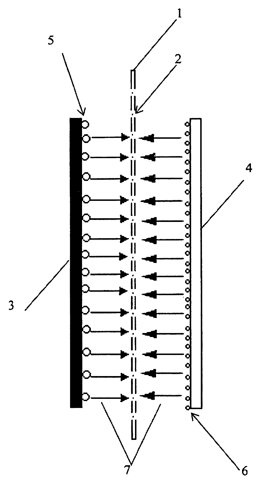
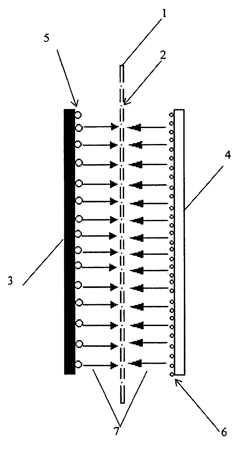
[0008]The present disclosure provides a composite membrane for a supercapacitor and its method of manufacture, as well as a supercapacitor using such membrane. The composite membrane promotes the combination of hydrogen and oxygen that is produced by the supercapacitor and that accumulates inside the supercapacitor to produce water that is absorbed in the electrolyte. This reduces pressure inside the supercapacitor, removes the hazards associated with increased pressure inside the supercapacitor, and reduces the usage of electrolyte in the supercapacitor. By reducing pressure inside the supercapacitor, the present disclosure also permits the complete enclosure of supercapacitors and their components.
[0009]The composite membrane can effectively promote the rapid combination of hydrogen and oxygen produced by supercapacitors, especially in electric vehicles such as electric buses, electric cars, and hybrid vehicles that operate under high power and high load conditions. It also can increase the precipitation potential of hydrogen and oxygen as water and raise the electrochemical potential window of supercapacitors during operation to improve the available energy density of the supercapacitor system.
[0022]The composite membrane for the supercapacitor for vehicles and other electric-powered devices of the invention not only reduces the maintenance of such supercapacitors, but also increases the energy density of the supercapacitor system, thus improving the comprehensive performance of the supercapacitor.

Problems solved by technology

However, a consequence of operating in a long-term over-charge / discharge mode is an increase in internal pressure caused by the internal accumulation of hydrogen and oxygen gas produced by the supercapacitors.
The increased pressure results in the safety valve of the supercapacitor remaining open all the time.
The problem this condition creates is that (1) the supercapacitor system can only be used in a valve-regulated mode, which requires electrolytes to be added on a regular basis so that the supercapacitor cannot be used maintenance-free, and (2) the long-term over-charge / discharge state accelerates the degradation of the activated material in the supercapacitor anode, reducing the life cycle of the supercapacitor.
During operation, a large volume of gases accumulates at the positive and negative electrodes around the supercapacitor membrane, thereby reducing the efficiency of the supercapacitor.
Although this situation creates favorable conditions for combining the hydrogen and oxygen gas to reduce the internal pressure, known membranes are not able to catalyze or otherwise promote the combination of hydrogen and oxygen.

Method used


Image

  • Composite membrane for a capacitor
  • Composite membrane for a capacitor

Examples


example 1

[0032]In a sealed stirrer such as a magnetic stirrer, add poly(ethylene oxide), 10 wt. % Pt / C (such as carbon-supported platinum nanoparticles produced by Johnson Matthey) into an acetonitrile solution to form a mixture. The content of the poly(ethylene oxide) is 6-15 grams, preferably 8-10 grams, and most preferably 9 grams. The content of the 10 wt. % Pt / C is 150-210 mg, preferably 170-190 mg, and most preferably 180 mg. The acetonitrile solution is 200-1000 ml, and preferably 400-800 ml. The temperature of the solution was maintained at about 60° C. to about 80° C. The mixture was placed into a sealed container and an inert gas was added to the sealed container. The mixture was continually stirred for at least 18 hours under protection of the inert gas until the mixture gets into solution. Then, the solution was transferred to a glass container. A polypropylene membrane (such as Celgard™) was placed in the container and soaked in the solution mixture for 1-2 hours. Then, the memb...

example 2

[0034]In another example, an ultrasound stirrer was used to stir the solution mixture. A dispersion resin such as a cationic 5 wt. % proton curing exchange membrane resin (such as Nafion™ produced by DuPont Company) and 10 wt. % Pt / C catalyst (such as carbon-supported platinum nanoparticles produced by Johnson Matthey) were mixed in an isopropyl alcohol solvent to make a mixture. The content of the cationic 5 wt. % proton curing exchange membrane resin was 5-15 grams, preferably 8-12 grams, and most preferably 10 grams. The content of the 10 wt. % Pt / C catalyst was 150-250 mg, preferably 190-210 mg, and most preferably 200 mg. The content of isopropyl alcohol solvent was 200-400 ml, preferably 280-320 ml, and most preferably 300 ml. The mixture was stirred continually for about 30-60 minutes with an ultrasonic stirrer to form a slurry mixture. The slurry mixture was sprayed onto both sides of a polypropylene membrane (e.g., a membrane produced by Celgard™). The membrane was dried in...

example 3

[0036]In this example, asbestos fibers, polyvinyl alcohol and 10 wt. % Pt / C (such as carbon-supported platinum nanoparticles produced by Johnson Matthey) were mixed through a wet papermaking method to make a 30-60 μm thick composite membrane. The content of asbestos fibers was 30-75 grams, preferably 40-60 grams, and most preferably 50 grams. The content of polyvinyl alcohol was 1-5 grams, preferably 2-4 grams, and most preferably 3 grams. The content of the 10 wt. % Pt / C was 200-600 mg, preferably 300-500 mg, and most preferably 400 mg.

[0037]A supercapacitor cell was made with the composite membrane of this example and a high power test was conducted on the cell. Compared with regular membranes, the test results showed that no obvious gas release was seen when the overcharge potential reached 1.75 V for the composite membrane of this example as compared with a regular membrane under the same test conditions.


PUM

PropertyMeasurementUnit
thicknessaaaaaaaaaa
temperatureaaaaaaaaaa
thicknessaaaaaaaaaa

Abstract

A composite membrane for a capacitor, comprising: a carrier; a mixture of a catalytic material for catalyzing hydrogen and oxygen, and a dispersion resin. The catalytic material is selected from the group consisting of a precious metal in Group VIII of the periodic table of elements and their alloys, and a rare earth metal of the La group of rare earth metals and their alloys. The carrier is a film formed by at least one of the following: polypropylene, polyethylene, polytetrafluoroethylene and polyamide. The carrier can include asbestos fibers, polypropylene fibers, or their mixture. The dispersion resin can be one of the following: ethylene, Nafion™, polyvinyl alcohol, polyethylene, CMC, and the like. The present disclosure also provides a method for making a composite membrane, and a capacitor with the composite membrane.

Description

CROSS-REFERENCE TO RELATED APPLICATIONS[0001]This Nonprovisional application claims priority under 35 U.S.C. §119(a) on Patent Application No(s). 200810042585.8 filed in the People's Republic of China on Sep. 2, 2008, the entire contents of which are hereby incorporated by reference.TECHNICAL FIELD[0002]The present disclosure relates to a composite membrane for capacitors and methods of manufacturing such membranes, and capacitors using such membranes. In particular, it relates to a composite membrane for asymmetric supercapacitors having an anode and cathode made of different materials, methods of manufacturing such membranes, and capacitors using such composite membranes. Capacitors with such composite membranes can be used in electric vehicles, electrically-powered devices, and other related technologies in the field to provide an energy-saving and environmentally-friendly power source.BACKGROUND[0003]Capacitors such as supercapacitors (also known as ultracapacitors) have found i...

Claims


Application Information

Patent Timeline
Patent Type & Authority Patents(United States)
IPC IPC(8): H01G9/00H01G9/02
CPCH01G9/02H01G9/155Y02E60/13H01G11/52H01G11/84
Inventor HUA, LIMIAO, XIAO LICHEN, XIAO LIN
Owner SHANGHAI AOWEI TECH DEV
Learn More