Volume and failure management method on a network having a storage device

a failure management and volume technology, applied in the field of storage systems, can solve the problems of high management cost, time required in taking a measure against failures, difficult to grasp the configuration of the system, etc., and achieve the effect of enhancing the freedom of the volume configuration

Inactive Publication Date: 2006-06-15
HITACHI LTD
View PDF55 Cites 26 Cited by
  • Summary
  • Abstract
  • Description
  • Claims
  • Application Information

AI Technical Summary

Benefits of technology

[0015] Providing a virtual volume using the virtualization device enhances the freedom of a volume configuration to be provided to the host computer. However, the SAN administrator is required to operate the SAN while always grasping both relationships, i.e. the relationship between a host comp

Problems solved by technology

The SAN's configuration becomes difficult to grasp as the scale of the SAN increases, i.e. as the connection relationship is complicated by the increase in the number of virtualization and storage devices.
Thus, there is a problem of high management cost.
However, beca

Method used


Image

  • Volume and failure management method on a network having a storage device
  • Volume and failure management method on a network having a storage device
  • Volume and failure management method on a network having a storage device

Examples


embodiment 1

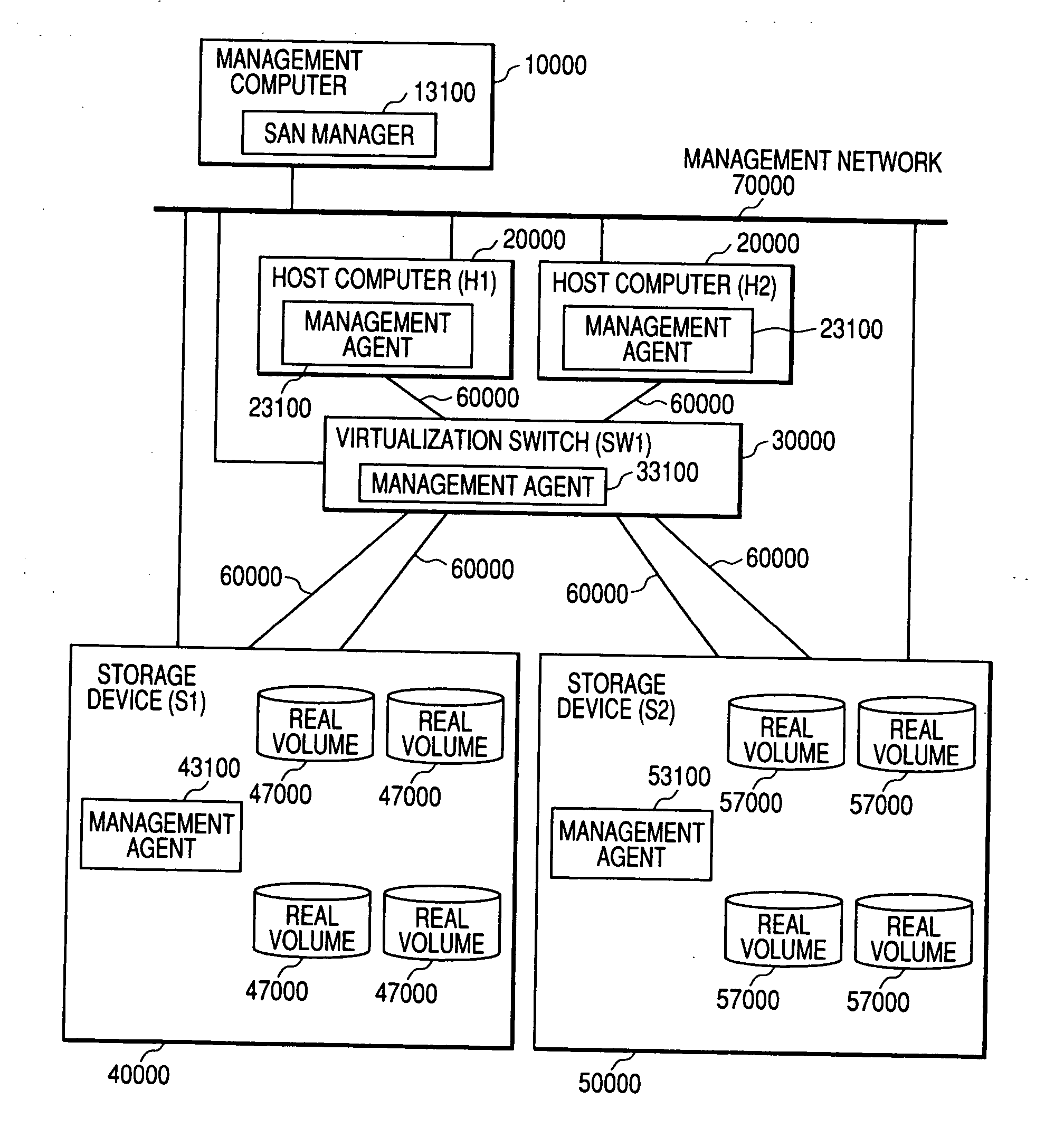
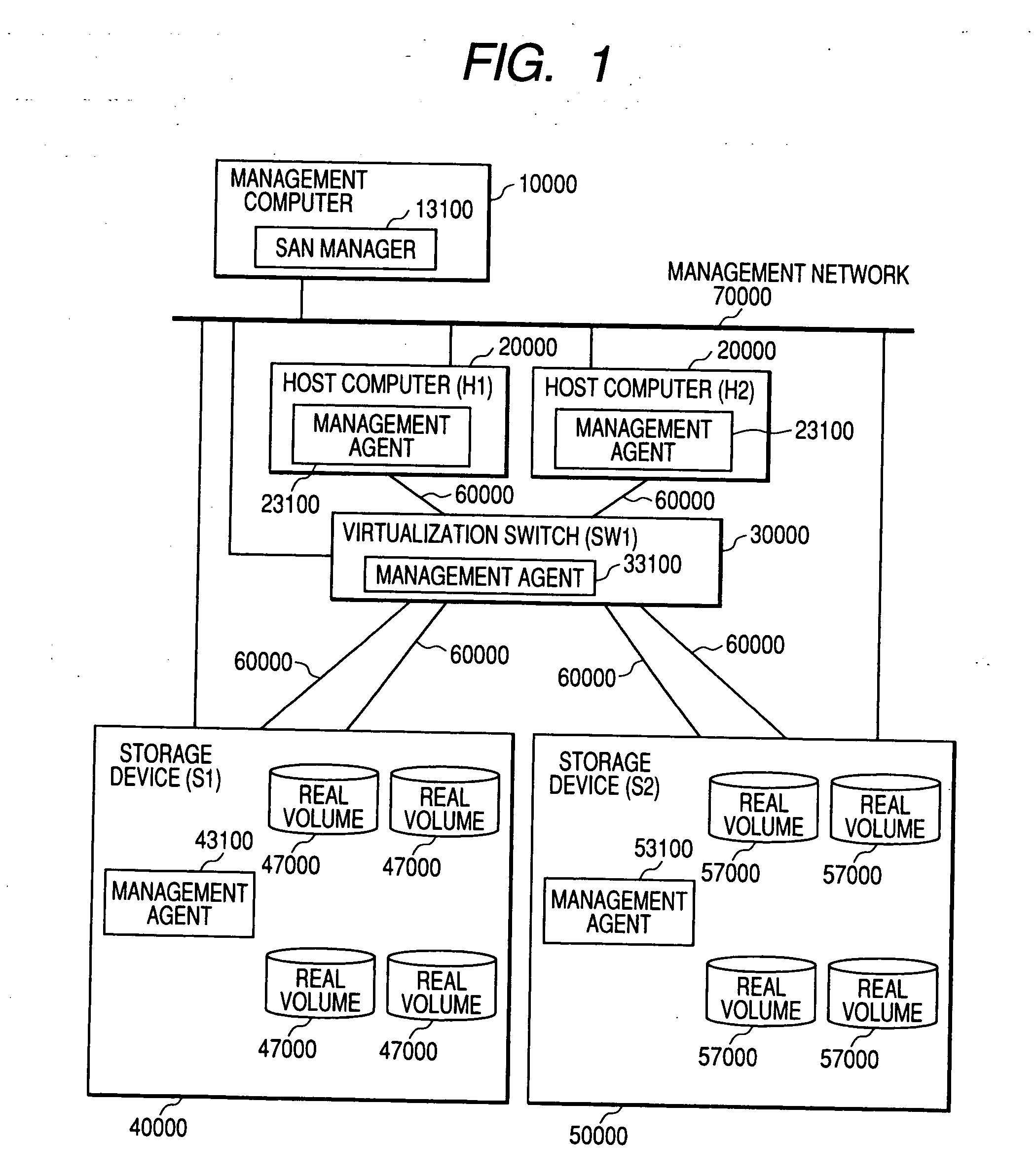
[0079]FIG. 1 illustrates a configuration example of the SAN. The SAN, in the invention, includes one or more host computers each having a management agent, one or more switches each having a management agent, one or more virtualization devices each having a management agent, one or more storage devices having a management agent, and one management computer having a SAN manager. On the SAN in embodiment 1, connection is assumed to be provided between two host computers (H1, H2) 20000, a virtualization switch (SW1) 30000 for playing a role as one switch-and-virtualization device, and two storage devices (S1, S2), through a fiber channel 60000, for the sake of convenience of the following explanations. Meanwhile, the management computer 10000 is connected to the host computers, the virtualization switches and the storage devices through a management network 70000 so that communication is possible between the management agent of each device and the SAN manager 13100 of the management co...

embodiment 2

[0186] The management computer 10000, the host computer 20000 and the storage device S250000 are similar in configuration to those of embodiment 2, and hence omitted to explain.

[0187]FIG. 30 shows a configuration example of the switch 80000 in this modification. The difference between the switch 80000 and the virtualization-and-switch 30000 in embodiment 2 lies in that there are stored, on a nonvolatile storage domain 83000 such as a hard disk, only a management agent 83100 as a program to communicate with the SAN manager 13100 and exchange the management information about the switch SW2 therewith, and an FC-connection management table 83200 as information representative of a connection relationship between the switch and the servers and storage devices through the fiber channel 60000. In other words, there are not stored a volume virtualization program 33200 and a virtual-volume management table 33500.

[0188]FIG. 31 shows a detailed configuration example of the virtualization stora...


PUM


Abstract

A SAN manager acquires configuration information from devices constituting a SAN and produces a corresponding relationship between a host computer and a virtual volume (virtual volume mapping) and a corresponding relationship between the host computer and a real volume (real volume mapping). Based on those pieces of mapping information, the SAN manager outputs a corresponding relationship between virtual and real volumes. Meanwhile, the failure notification messages received from the in-SAN devices are construed to detect and output an influence of the failure upon the access to a real or virtual volume. Furthermore, when receiving a plurality of failure notifications from the devices connected to the SAN, the plurality of failure notifications are outputted with an association based on the corresponding relationship between real and virtual volumes.

Description

CROSS-REFERENCES [0001] This application is a continuation-in-part (CIP) application of U.S. application Ser. No. 10 / 659,362, filed Sep. 11, 2003, and U.S. application Ser. No. 10 / 355,899, filed Jan. 31, 2003. These applications in turn claim priority, respectively, from Japanese Patent Application No. 2003-189954, filed on Jul. 2, 2003, and Japanese Patent Application No. 2002-293150, filed Oct. 7, 2002. The entire disclosures of all of these applications are incorporated herein by reference.BACKGROUND [0002] The present invention relates to a storage system for use in a computer system. More particularly, the invention relates to a method and apparatus for managing a volume configuration and failure, on a storage area network (hereinafter, referred to as SAN) such that the real volume provided from a storage system is to be provided as a virtual volume to a host computer through a volume virtualization function of a virtualization device. [0003] (1) SAN [0004] Recently, there is a...

Claims


Application Information

Patent Timeline
IPC IPC(8): G06F11/00
CPCG06F3/0605G06F3/0665G06F3/067G06F11/0727G06F11/0775G06F11/0781G06F11/079H04L41/0213H04L41/046H04L41/065H04L41/08H04L41/12H04L41/22H04L41/40H04L41/342
Inventor YAMAMOTO, MASAYUKIOEDA, TAKASHI
Owner HITACHI LTD
Why Eureka
Try Eureka