
Rubber boot-based roof flashing apparatus

a rubber boot and roof flashing technology, which is applied in lighting and heating apparatus, ventilation systems, heating types, etc., can solve the problems that chimney pipes flashed using rubber boots tend to fail to meet applicable wind loading test standards, and the use of rubber boot flashing is not feasibl

Active Publication Date: 2006-06-22
CARDINAL IP HLDG LLC
View PDF15 Cites 48 Cited by
  • Summary
  • Abstract
  • Description
  • Claims
  • Application Information

AI Technical Summary

Benefits of technology

[0004] In carrying out principles of the present invention, in accordance with a representatively illustrated embodiment thereof, a specially designed flashing adapter kit is provided for use in conjunction with a rubber flashing boot to flash a hot gas vent conduit, representatively a chimney pipe, at a roof opening through which it extends. Use of the flashing kit enables the overall rubber boot-based chimney flashing structure to be UL certified due to the adapter kit's prevention of the boot from reaching unacceptably high operating temperatures, and also braces the chimney pipe to an extent permitting it to meet applicable wind load test standards.
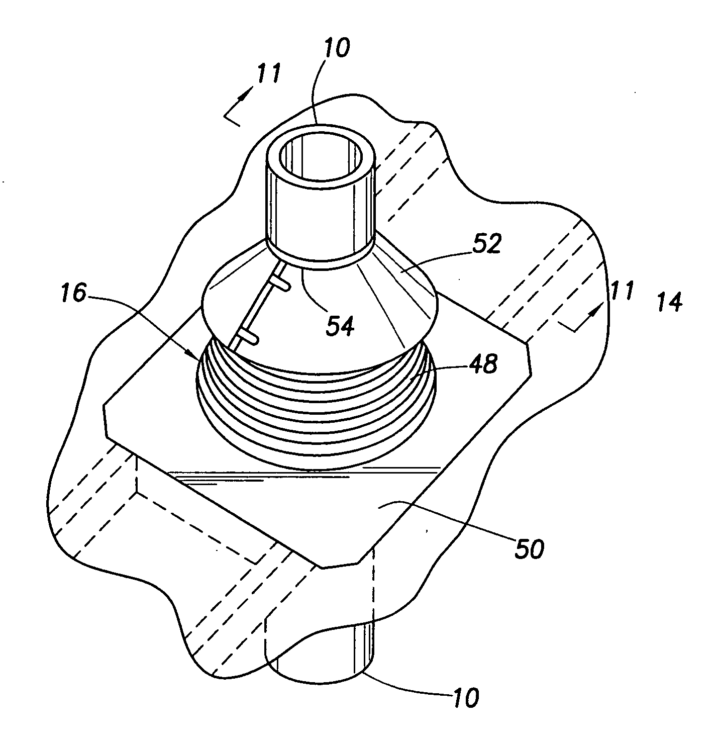
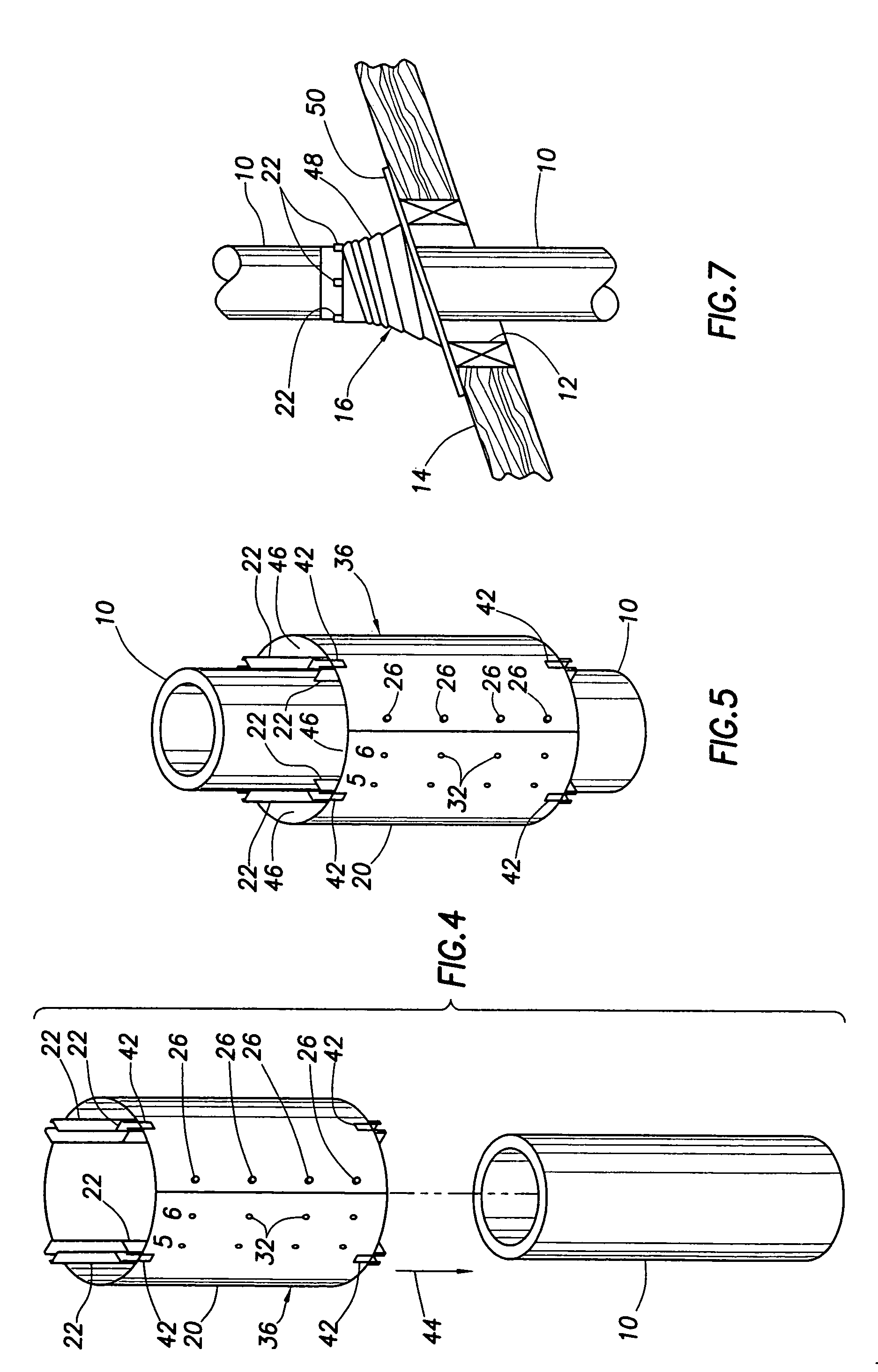
[0010] Thus, the portion of the rubber boot through which the chimney pipe upwardly extends is spaced apart by the sleeve from the rubber boot and is air insulated from the hot chimney pipe. Hot air which might potentially build up in the cooling passages between circumferentially adjacent pairs of the vertical spacer members is simply permitted to vent outwardly from the open upper ends of such cooling passages, as well as vertically through the interiors of the channel-shaped spacer members, and be downwardly discharged through the interior of the storm collar. The bracing of the sleeve to the roof, by the aforementioned connection members, also braces the chimney pipe portion extending through the sleeve to an extent permitting the overall flashed chimney apparatus to meet applicable wind load test standards.

Problems solved by technology

However, in the past this use of a rubber flashing boot has not been feasible since the necessary UL safety certification for this flashing application has not been obtainable due to the impermissibly high boot temperature levels resulting during the flow of hot combustion products through the chimney pipe.
Additionally, chimney pipes flashed using rubber boots tend to fail to meet applicable wind loading test standards.

Method used


Image

  • Rubber boot-based roof flashing apparatus
  • Rubber boot-based roof flashing apparatus
  • Rubber boot-based roof flashing apparatus

Examples


Embodiment Construction

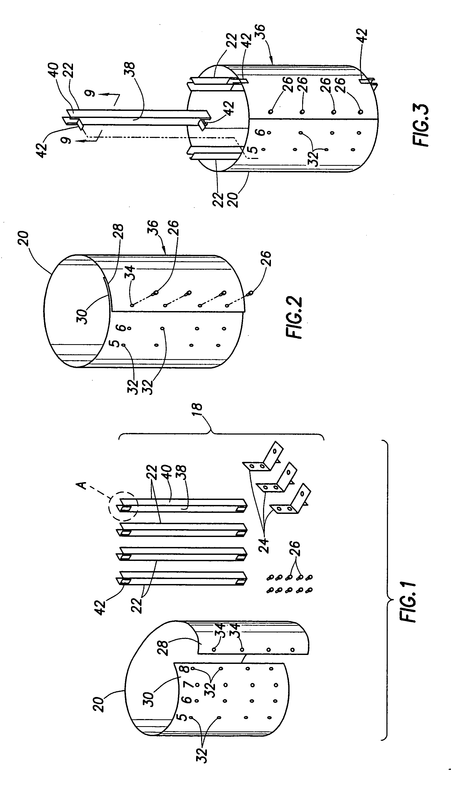
[0023] AS illustrated in the accompanying drawing FIGS. 1-11, the present invention provides apparatus and methods for flashing a metal chimney pipe 10 (see FIGS. 6 and 7), which extends through an opening 12 in a roof 14, utilizing a conventional rubber flashing boot 16 (see FIGS. 7 and 8) which may alternatively be a flashing boot of another resilient material such as a suitable plastic-based material. Due to the subsequently discussed unique configuration of the flashing apparatus, the overall through-roof chimney installation is able to incorporate the rubber boot 16 and still be UL certified—meeting both the thermal and structural (wind load) requirements in the UL standards.

[0024] The flashing apparatus of the present invention is representatively incorporated in a convenient flashing adapter kit 18 (see FIG. 1) which includes a rectangular sheet metal sleeve panel 20, four elongated metal spacer channels 22, three generally L-shaped sheet metal connection brackets 24, and te...


PUM


Abstract

To flash a hot gas vent pipe, representatively a chimney pipe, extending upwardly through a roof opening, a tubular sleeve having vertically extending spacer members interiorly secured thereto, with upper ends projecting above the upper sleeve end, is concentrically placed around the chimney pipe and anchored to the roof. A rubber boot is then placed around the sleeve and secured to the roof. Finally, a storm collar is downwardly telescoped onto the chimney pipe and rests on the upper end of the sleeve spacer members. Vertical cooling passages are defined between adjacent spacer member pairs, and through their interiors, and have upper exit portions communicating with the storm collar interior.

Description

BACKGROUND OF THE INVENTION [0001] The present invention generally relates to the flashing of chimneys and other hot gas vent conduit structures extending through roofs and, in a representatively illustrated embodiment thereof, more particularly provides novel roof flashing apparatus which permits a rubber boot to be utilized in the flashing of a metal chimney pipe extending through a roof opening without subjecting the rubber boot to an undesirably high temperature during firing of the fuel-fired heating apparatus with which the chimney pipe is operatively associated. [0002] Rubber flashing boots are commonly used as flashing structures for sealing around non-heated pipes, such as plumbing fixture vent pipes, extending through roof openings. For a variety of reasons it would be desirable to utilize a rubber boot to flash around a heated pipe, such as a metal chimney pipe, extending through a roof opening. However, in the past this use of a rubber flashing boot has not been feasible...

Claims


Application Information

Patent Timeline
IPC IPC(8): E04D13/14
CPCE04D13/1476F16L5/00F23J13/02F23J2213/301F23J2213/302
Inventor EDGAR, GLEN A.CARR, RODNEY L.NEWHOUSE, SCOTT A.
Owner CARDINAL IP HLDG LLC
Learn More