Engine speed control with high speed override mechanism

a technology of high-speed override and engine speed control, which is applied in the direction of engine controllers, speed sensing governors, machines/engines, etc., can solve the problems of time lag between, speed back, and engine speed decrease, so as to reduce the number of parts needed, increase the running speed of the engine, and more compact arrangement

Active Publication Date: 2006-06-22
CERTIFIED PARTS
View PDF21 Cites 15 Cited by
  • Summary
  • Abstract
  • Description
  • Claims
  • Application Information

AI Technical Summary

Benefits of technology

[0013] In a further embodiment, the engine includes a primary speed control mechanism connected to the governor lever, and a secondary speed control mechanism including a secondary speed control lever mounted to a common shaft with the primary speed control lever and throttle actuator lever of the primary speed control mechanism to provide a more compact arrangement and reduce the number of parts needed. The secondary speed control lever is rotatable independently of the primary speed control lever and the throttle actuator lever about their common shaft to engage the throttle actuator lever upon actuation by an operator to override the primary speed control mechanism to temporarily the increase the running speed of the engine.
[0014] In a still further embodiment, the secondary speed control mechanism includes an electrical actuator element, such as a solenoid, connected to the secondary speed control lever. T

Problems solved by technology

One disadvantage of the foregoing speed control arrangement is that if a load is imposed upon the engine, such as by a lawnmower encountering tall grass or a snow thrower encountering deep or heavy snow, for example, there is often a time lag between the imposition of the load and decrease in engine speed, and the response of the governor to corr

Method used


Image

  • Engine speed control with high speed override mechanism
  • Engine speed control with high speed override mechanism
  • Engine speed control with high speed override mechanism

Examples


second embodiment

[0047] A secondary speed control mechanism according to the present invention is shown in FIGS. 4-6. The embodiment of FIGS. 4-6 includes several components which are identical to those of FIGS. 1-3, and identical reference numerals have been used to indicate identical or substantially identical components therebetween.

[0048] Referring to FIG. 4, engine 10 includes primary speed control mechanism 100 including primary speed control lever 102 attached to mount plate 104 of engine 10 at pivot 106, which includes handle 108 extending through slot 110 in mount plate 104. Handle 108 may be grasped by an operator to move primary speed control lever 102 between a stop position, shown in FIG. 4, in which primary speed control lever 102 contacts the lower end of slot 110, and a high engine running speed position, shown in FIG. 5, in which primary speed control lever 102 contacts the upper end of slot 110. Lower arm 112 of primary speed control lever 102 is attached to flange 114 of governor ...

third embodiment

[0052] Secondary speed control mechanism 150 according to the present invention is shown in FIGS. 7-9. The embodiment of FIGS. 7-9 includes several components which are identical to those of the embodiment of FIGS. 1-3 discussed above, and identical reference numerals have been used to indicate identical or substantially identical components therebetween. Additionally, while only selected components of the primary and secondary speed control mechanisms are shown in FIGS. 7-9 for clarity, it should be understood that the foregoing mechanisms are part of engine 10, described above, or a similar engine.

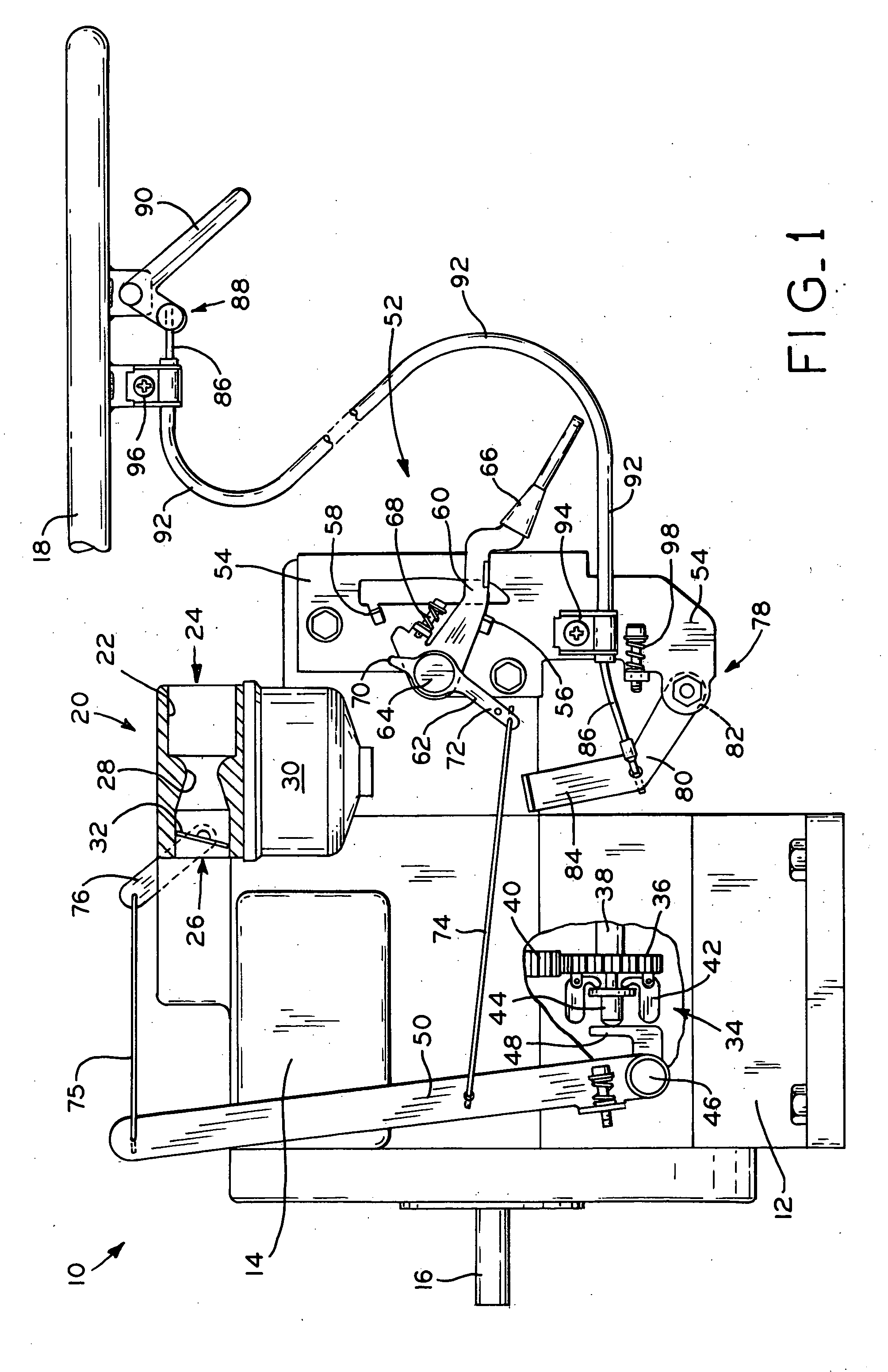
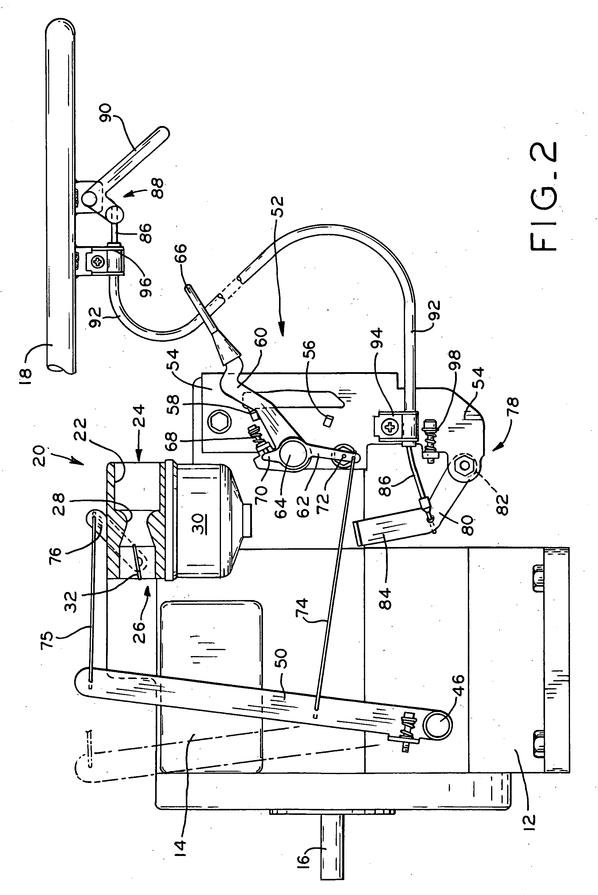
[0053] Referring first to FIG. 7, engine 10 includes primary speed control mechanism 52, described above, including primary speed control lever 60 and throttle actuator lever 62 each pivotally mounted at a common pivot 64, such as shaft 148, for example. Secondary speed control mechanism 150 of the third embodiment includes secondary speed control lever 152 also pivotally mounted to shaf...

fourth embodiment

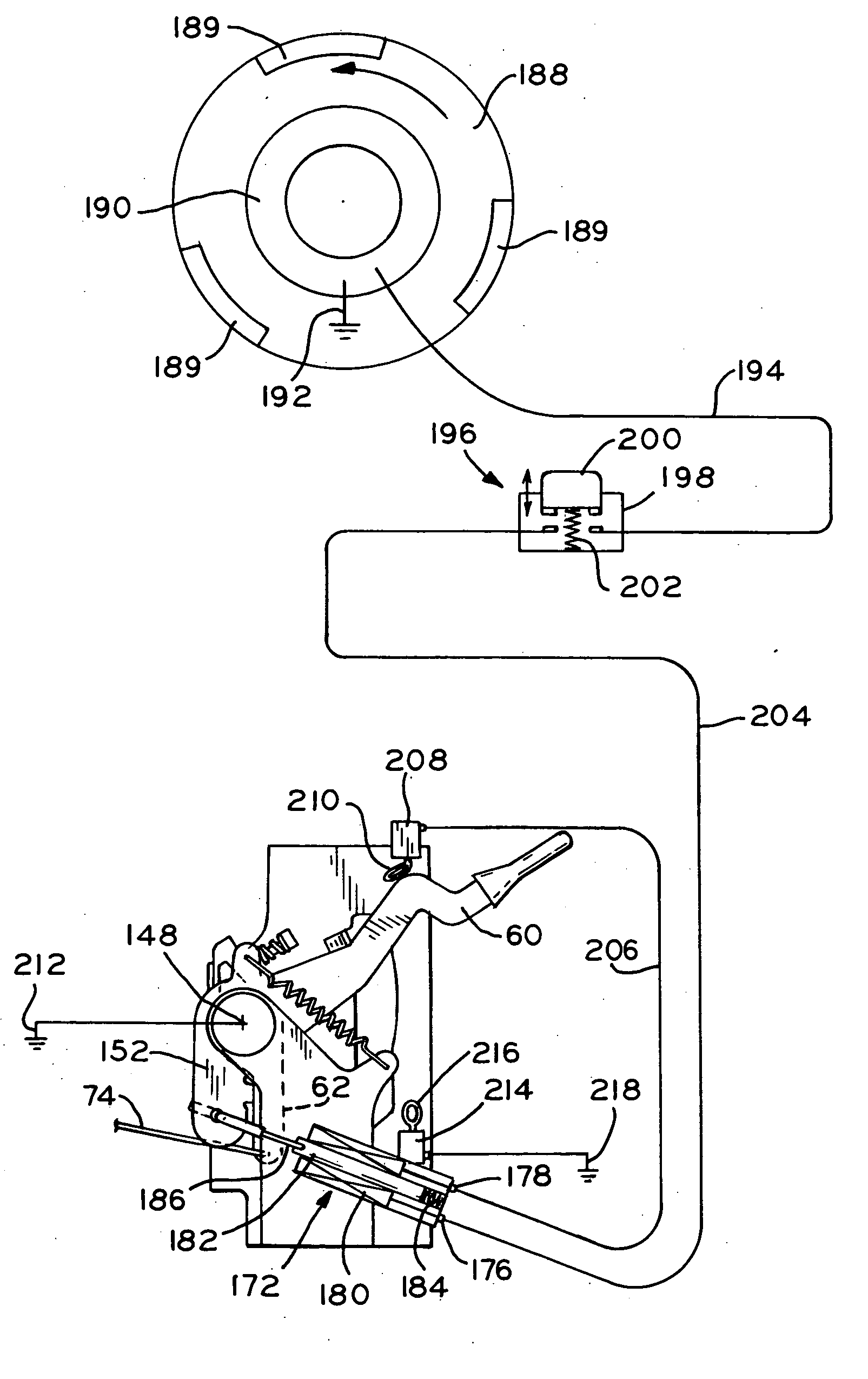
[0056] Referring to FIGS. 10A-12, secondary speed control mechanism 170 according to the present invention is shown. The embodiment of FIGS. 10A-12 includes several components which are identical to the embodiments of FIGS. 1-3 and 7-9 described above, and identical reference numerals have been used to indicate identical or substantially identical components therebetween. Additionally, while only selected components of the primary and secondary speed control mechanisms are shown in FIGS. 10A-12 for clarity, it should be understood that the foregoing mechanisms are part of engine 10 described above or a similar engine.

[0057] Referring to FIG. 10A, secondary speed control mechanism 170 includes secondary speed control lever 152, described above with reference to secondary speed control mechanism 150. Secondary speed control mechanism 170 also includes an electrical actuator element, shown in FIGS. 10A, 11A and 12 as a solenoid 172 mounted to mount plate 54 for actuating secondary spee...


PUM


Abstract

A secondary engine speed control mechanism for small internal combustion engines, including an operator control which is manually operable to override an engine running speed which is set by the engine's primary speed control mechanism and governed by the governor. The secondary speed control mechanism may be selectively actuated by the operator in anticipation of an increased engine load to provide a temporary increase or “boost” to engine speed above the set, governed engine running speed. The secondary speed control mechanism may be either mechanically or electrically actuated, and may include an operator actuated, trigger-type mechanism or an electrical switch located on the handle of an implement with which the engine is used.

Description

CROSS REFERENCE TO RELATED APPLICATIONS [0001] This application is a continuation-in-part of U.S. patent application Ser. No. 11 / 014,499, entitled ENGINE SPEED CONTROL WITH HIGH SPEED OVERRIDE MECHANISM, filed on Dec. 16, 2004.BACKGROUND OF THE INVENTION [0002] 1. Field of the Invention [0003] The present invention relates to small internal combustion engines of the type used with lawnmowers, lawn tractors, other utility implements, and in sport vehicles, for example. In particular, the present invention relates to speed control mechanisms for such en gines. [0004] 2. Description of the Related Art [0005] Small internal combustion engines typically include a carburetor which supplies an air / fuel mixture to one or more combustion chambers of the engine for combustion to drive the piston(s) and the crankshaft of the engine. The engine speed is typically regulated by a throttle valve disposed within the intake passage of the carburetor, which is movable between a substantially closed p...

Claims


Application Information

Patent Timeline
IPC IPC(8): F02D31/00F02D11/10
CPCF02D11/04F02D11/105F02D11/107F02D31/002F02D2009/023F02D2011/102F02D2250/16
Inventor WETOR, CLYDESTOUT, THOMASSTENZ, GARYSCHNEIDER, DANIEL
Owner CERTIFIED PARTS
Why Eureka
Try Eureka