Radio frequency tuner

a radio frequency tuner and frequency technology, applied in the field of radio frequency tuners, can solve the problems of reducing the noise figure achievable, insertion loss, and generally not well controlled channel power range, so as to achieve acceptable isolation, reduce the cost, and avoid degradation of performance with time. the effect of relay degradation

Inactive Publication Date: 2006-08-17
INTEL CORP
View PDF2 Cites 3 Cited by
  • Summary
  • Abstract
  • Description
  • Claims
  • Application Information

AI Technical Summary

Benefits of technology

[0025] It is thus possible to provide a tuner which can achieve acceptable isolation between signals from different distribution networks without requiring the presence of any RF relays. Thus, effects such as insertion loss and degradation of performance with time associated with such relays can be avoided. A relatively less expensive and more compact arrangement can be provided.

Problems solved by technology

However, the channel power range is generally not as well controlled as in the case of a cable distribution network so that channel power may vary from the thermal noise floor to, for example, 0 dBm.
Also, the presence of the relay 14 in the signal path to the input of the tuner 15 results in an insertion loss which degrades the noise figure achievable by the tuner 15.
Although a typical example of the relay 14 can achieve isolation of the order of 80 dB at lower frequencies within the frequency range of the distribution networks, the isolation reduces with increasing frequency and so results in a degradation in the carrier-to-noise performance.
Another disadvantage of the relay 14 is that, because it is a mechanical component, it exhibits degradation with time caused by repeated switching.
Such degradation may include, for example, an increase in insertion loss caused by the build-up of contact resistance.
This effect results in a reduction in noise figure and a degradation in impedance matching.
Further, because of increased levels of surface contaminants on the relay contacts, the intermodulation performance may become degraded with time as such contaminants can have semiconducting properties resulting in non-linear distortion generation.
A further disadvantage of the use of an RF relay is that devices of this type are generally only available as changeover or two-way switches and can therefore only switch between two distribution networks.
Apart from the additional cost and bulk of such further relays, some of the signals are subjected to the cumulative effects of having passed through several relays.

Method used


Image

  • Radio frequency tuner
  • Radio frequency tuner
  • Radio frequency tuner

Examples


Embodiment Construction

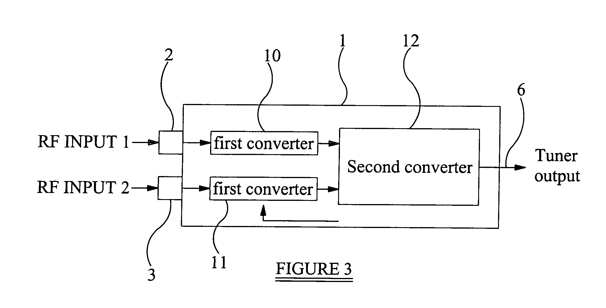
[0031] The tuner shown in FIG. 3 comprises an enclosure 31, two radio frequency inputs 32 and 33, and a tuner output 36 as described hereinbefore with reference to FIG. 1. The tuner of FIG. 3 further comprises first frequency changers or converters 40 and 41 whose inputs are connected to the RF inputs 32 and 33, respectively. The outputs of the converters 40 and 41 are connected to respective inputs of a second frequency changer or converter 42, whose output is connected to the tuner output 36.

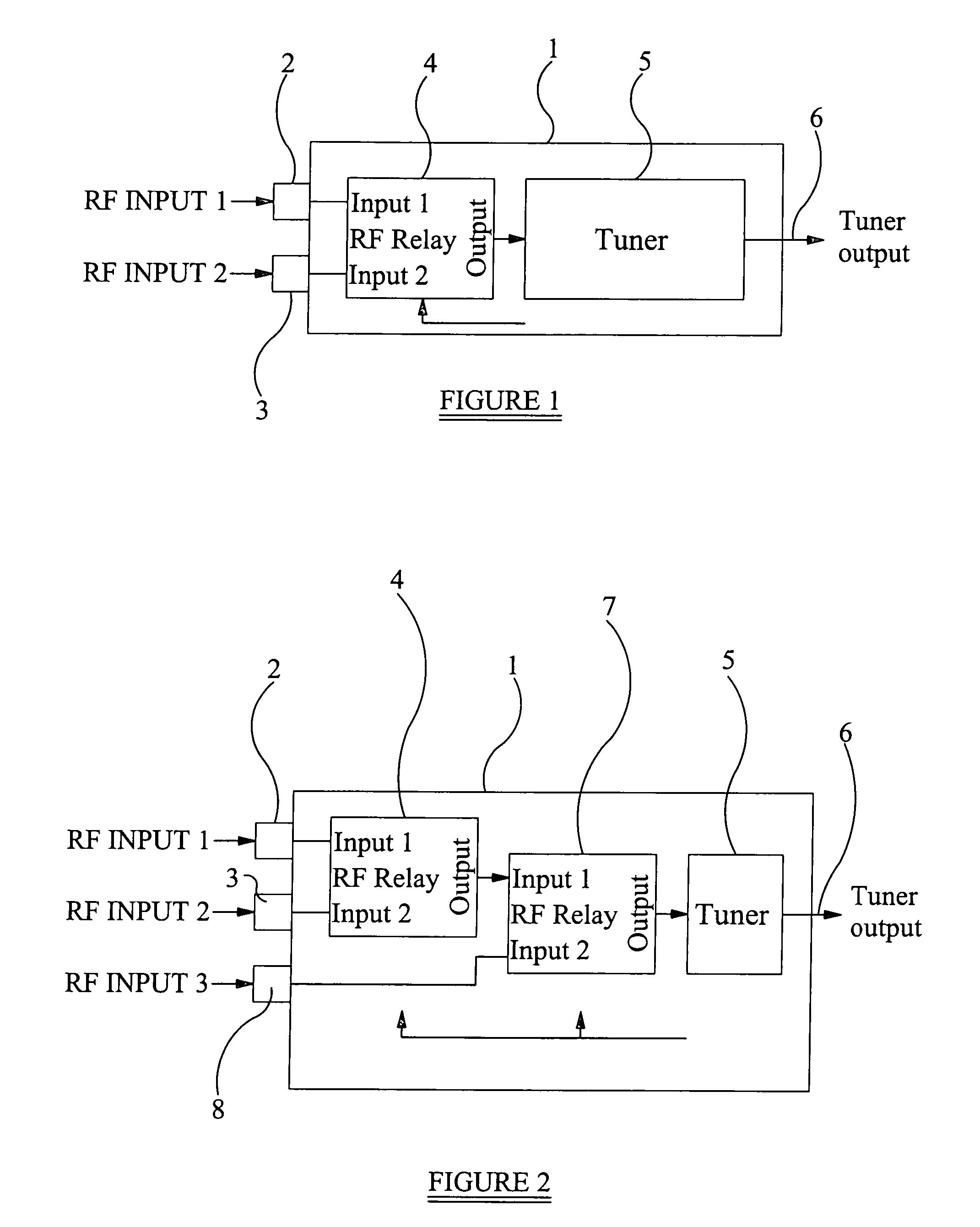
[0032] Although the tuner shown in FIG. 3 is intended for connection to two distribution networks, such a tuner may be arranged to receive signals from any number of distribution networks. In particular, each network requires an RF input connected to a respective frequency changer or converter, whose output is connected to a respective input of the single second converter 42.

[0033] As illustrated in FIG. 4, the first frequency changer or converter 50 comprises a mixer or multiplier 55 having...


PUM


Abstract

A radio frequency tuner is provided having inputs for receiving signals in common or overlapping frequency ranges from distribution networks. Each input is connected to a respective first converter, for example performing upconversion to a first intermediate frequency above the RF frequency ranges of the incoming signals. The first frequency changers are arranged to be active one at a time. The outputs of the first frequency changers are supplied to a second frequency changer which performs downconversion on the output signal of the active first converter to convert a selected channel from one of the distribution networks to a second intermediate frequency. Sufficient RF isolation may therefore be provided without requiring mechanical switching components such as RF relays.

Description

BACKGROUND OF THE INVENTION [0001] 1. Field of the Invention [0002] The present invention relates to a radio frequency tuner. Such a tuner may be used, for example, to receive and select signals from two or more radio frequency sources. [0003] 2. Description of the Related Art [0004]FIG. 1 of the accompanying drawings illustrates a tuner for receiving signals from a cable transmission network and a terrestrial transmission network and for selecting a channel from either network for reception. Tuners of this type are known as “Plug and Play”. Such a tuner is connected to two (or more) networks at the same time. Both networks contain channels within a frequency range which is typically from approximately 47 MHz to approximately 1100 MHz. It is also typical for the channel frequency allocation to be substantially identical between the networks such that the channels of one network occupy the same frequencies as the channels of the other network. [0005] In the case of a cable distributi...

Claims


Application Information

Patent Timeline
Patent Type & Authority Applications(United States)
IPC IPC(8): H04B7/08H04B1/18H03D7/16H04B1/00
CPCH03D7/165H04B1/0064H04B1/0075H04B1/18
Inventor COWLEY, NICHOLAS PAULCOE, PETER
Owner INTEL CORP
Why Eureka
Try Eureka