Suspended cable scaffold assembly

a technology of suspended cables and scaffolding, which is applied in the field of scaffolding, can solve the problems of occupying a lot, attempting to go beyond a reasonable height too costly to be realized in practice, and limited maximum height of the scaffolding, so as to achieve the effect of optimizing the access to the structur

Inactive Publication Date: 2006-06-22
STRUCTURE DACIER ORLEANS
View PDF18 Cites 19 Cited by
  • Summary
  • Abstract
  • Description
  • Claims
  • Application Information

AI Technical Summary

Benefits of technology

[0010] Advantageously, the suspended scaffold of the present invention may be mounted in a limitless number of configurations to allow proper access to a structure. The positioning of the support members further allows to easily design and modify these configurations before and after installation so that at all time access to the structure can be optimized.

Problems solved by technology

With this method, the maximum height of the scaffolding is limited by physical factors such as weight, installation and stability, making any attempt to go beyond a reasonable height too costly to be realized in practice.
Another disadvantage of the conventional bottom / up method of setting up a scaffold is that the resulting structure occupies a lot of space to provide proper balance and support to the whole scaffold system, obstructing access to the building at locations where the scaffold serves no purpose.

Method used


Image

  • Suspended cable scaffold assembly
  • Suspended cable scaffold assembly
  • Suspended cable scaffold assembly

Examples


Embodiment Construction

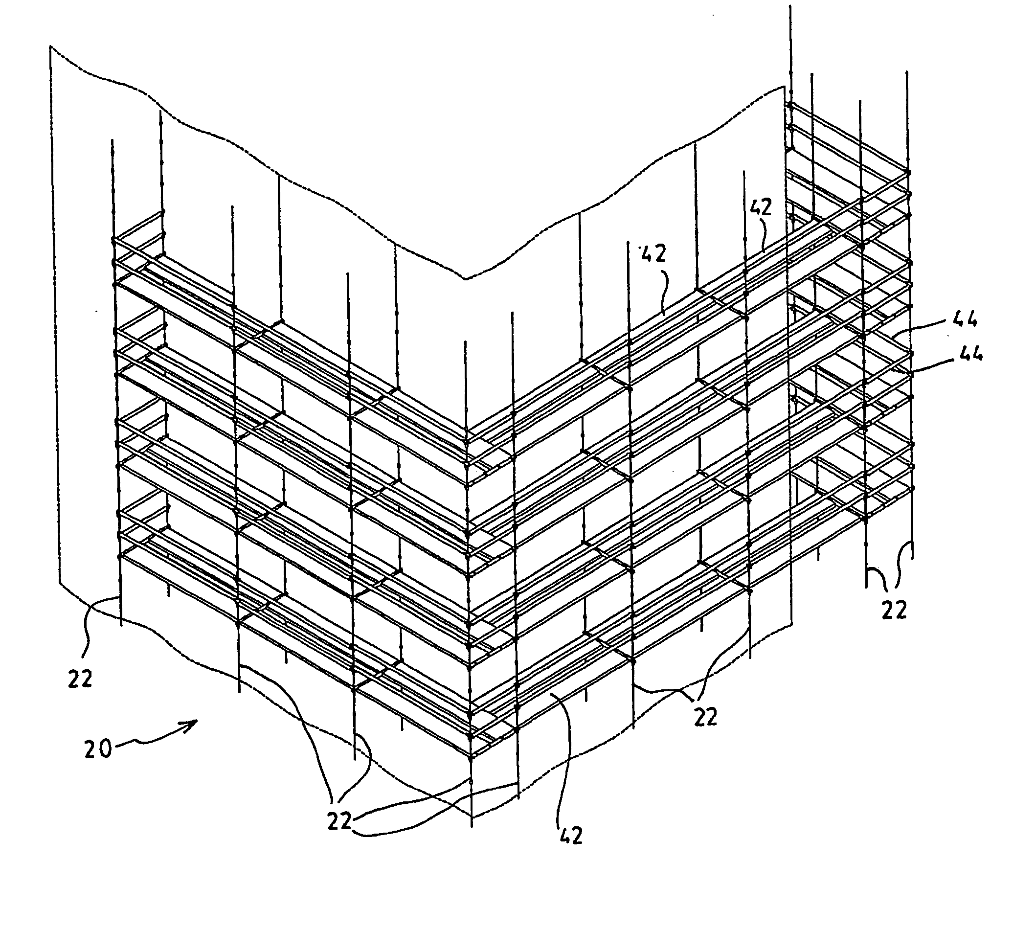
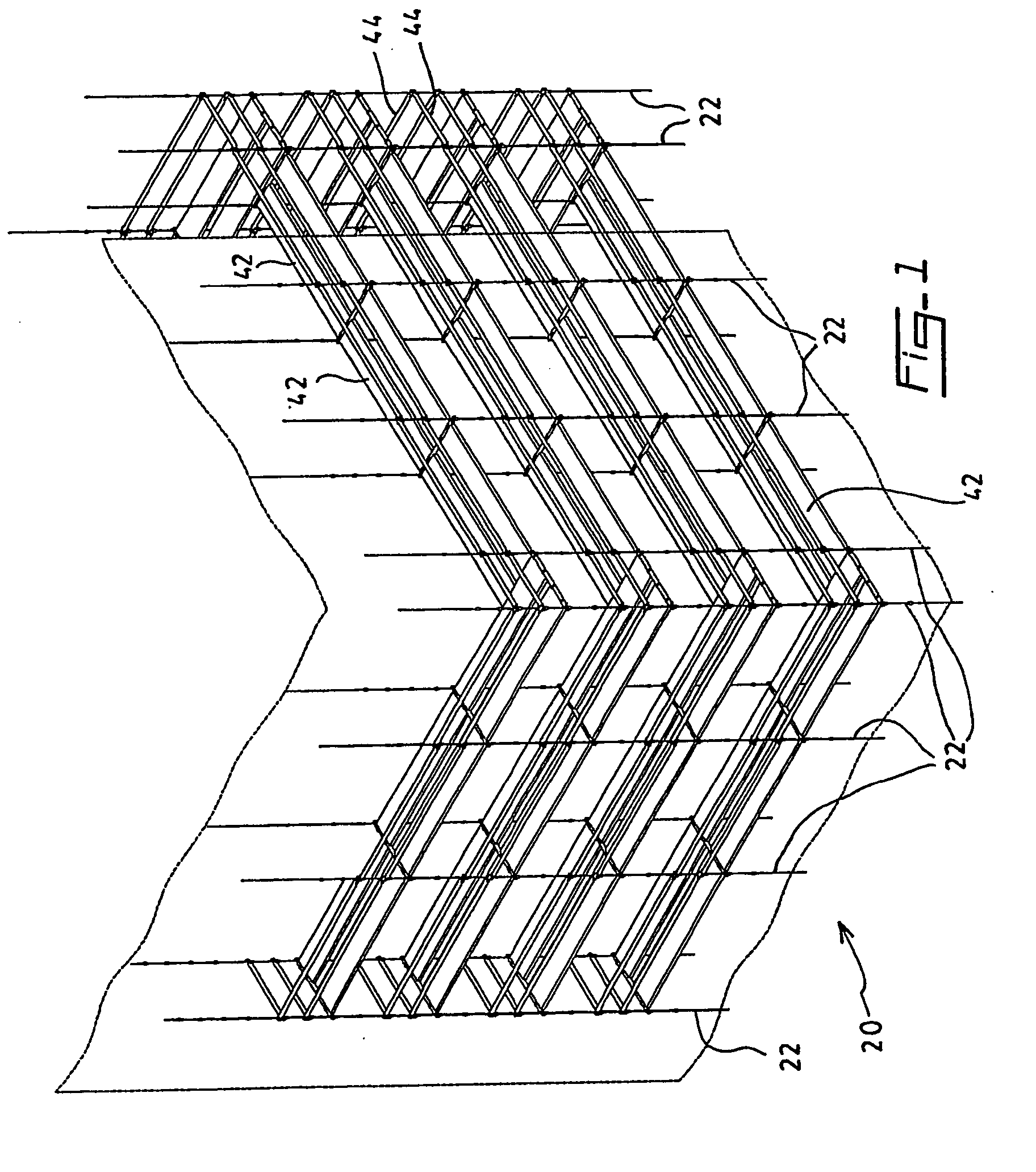
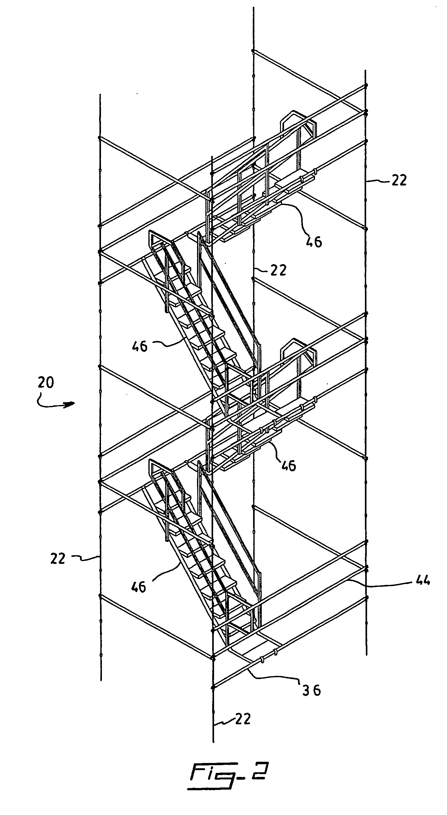
[0026] Referring to FIGS. 1 and 2, there is shown a suspended scaffold assembly 20 according to a preferred embodiment of the present invention. It is understood throughout the present description that the scaffold of the invention is intended to provide access to any appropriate structure, may it be a building or a vessel, for working on the side of or under a bridge, at the construction field of a multi-storied building or any other structure which needs to be accessed by a scaffold system, indoors or outdoors. It is a particularly advantageous feature of the present invention that it provides great flexibility of design so that it may be adapted to structures of a wide variety of shapes and heights.

[0027] The scaffold 20 includes a plurality of supporting cables 22. The number of cables in a given assembly may vary and is preferably sufficient to provide the necessary access to the structure. The cables are preferably made of threaded steel of ⅝″ of diameter, but could have diff...


PUM


Abstract

A versatile suspended scaffold assembly is provided. The scaffold assembly includes a plurality of suspended cables, each having a plurality of support elements pressed or clamped thereon at regular intervals, the distance between consecutive support elements being selected between 250 mm and 1000 mm, preferably about 500 mm. Beams are supported by the support elements on which platforms, guardrails and stairways may be mounted.

Description

FIELD OF THE INVENTION [0001] The present invention relates to the field of scaffoldings and more particularly concerns a versatile suspended cable scaffold assembly for use inside a building or a vessel, for working on the side of or under a bridge, at the construction field of a multi-storied building or the like. BACKGROUND OF THE INVENTION [0002] Conventional scaffoldings are erected by successively assembling pipes and related components vertically from the ground level up, along the exterior of a structure such as a building. With this method, the maximum height of the scaffolding is limited by physical factors such as weight, installation and stability, making any attempt to go beyond a reasonable height too costly to be realized in practice. Another disadvantage of the conventional bottom / up method of setting up a scaffold is that the resulting structure occupies a lot of space to provide proper balance and support to the whole scaffold system, obstructing access to the buil...

Claims


Application Information

Patent Timeline
Patent Type & Authority Applications(United States)
IPC IPC(8): E04G3/30E04G5/04E04G7/04
CPCE04G3/30E04G5/10
Inventor DUGUAY, FRANCOIS
Owner STRUCTURE DACIER ORLEANS
Why Eureka
Try Eureka