Load bearing structure and method of manufacture thereof

a technology of load bearings and bearings, applied in the direction of track superstructures, roads, constructions, etc., can solve the problems of depletion of natural resources, poor shock absorption characteristics, and poor vibration absorption characteristics of steel

Inactive Publication Date: 2006-06-22
GENERAL ELECTRIC CO
View PDF7 Cites 33 Cited by
  • Summary
  • Abstract
  • Description
  • Claims
  • Application Information

AI Technical Summary

Benefits of technology

[0004] Briefly, in accordance with one embodiment of the invention, there is provided a load bearing structure. The load bearing structure is configured to bear a load, the load bearing structure includes a number of cells and the load bearing structure has a length, a center, and a cell density. The cell density of the load bearing structure varies along the length. The load bearing structure has a mass of 6 kg or more.

Problems solved by technology

Concrete is typically a very rigid material and therefore has poor shock absorption characteristics, while steel also suffers from poor vibration absorption characteristics, while use of wood is increasingly being discouraged because it results in depletion of natural resources.
In fact, in many countries, policies discontinuing the use of wooden sleepers have been affected.
These conceptualizations, however, suffer from a number of disadvantages, such as high weight, leading to an increase in material costs, and low strength to weight ratios, among others.

Method used


Image

  • Load bearing structure and method of manufacture thereof
  • Load bearing structure and method of manufacture thereof
  • Load bearing structure and method of manufacture thereof

Examples


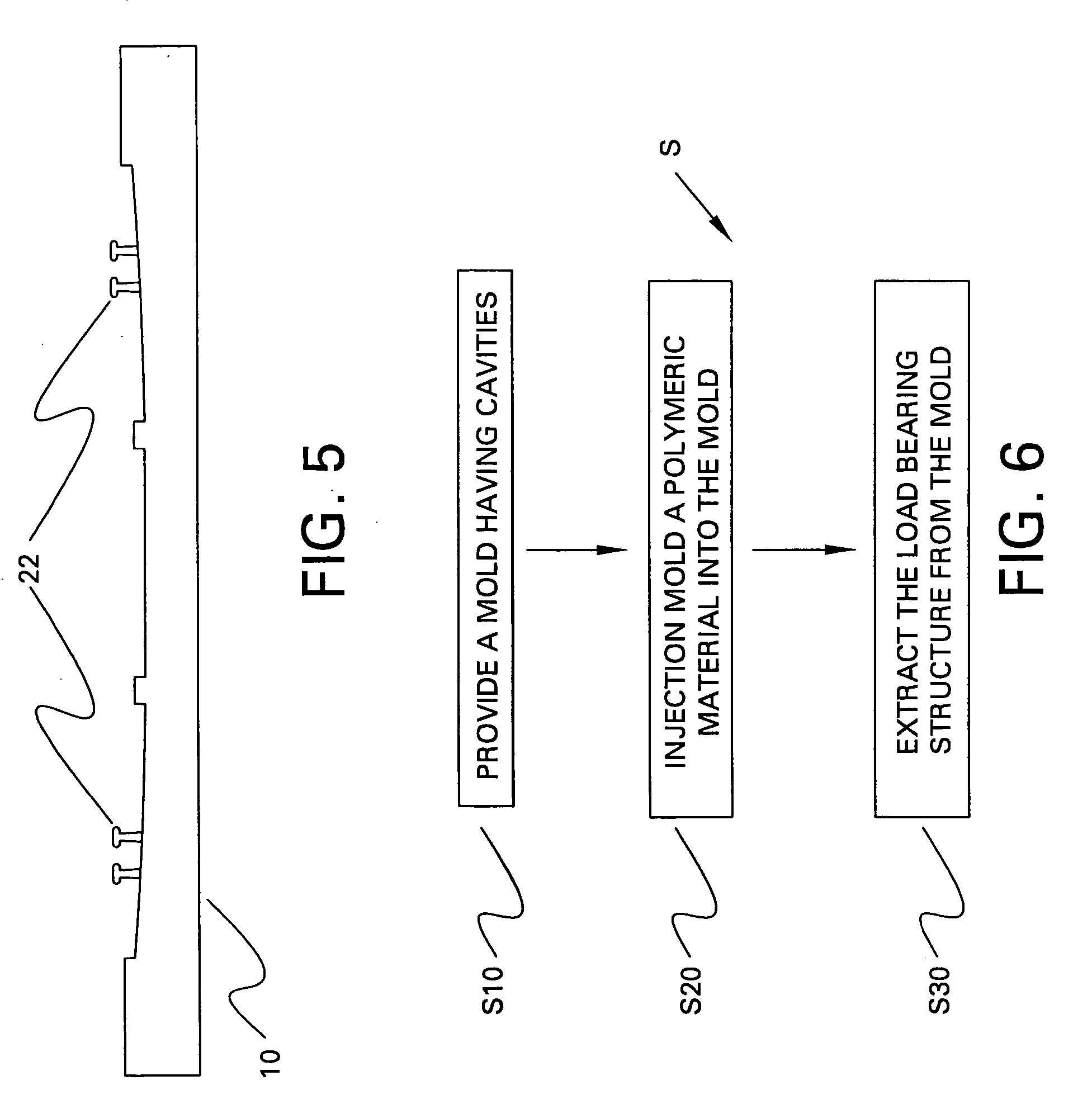
Embodiment Construction

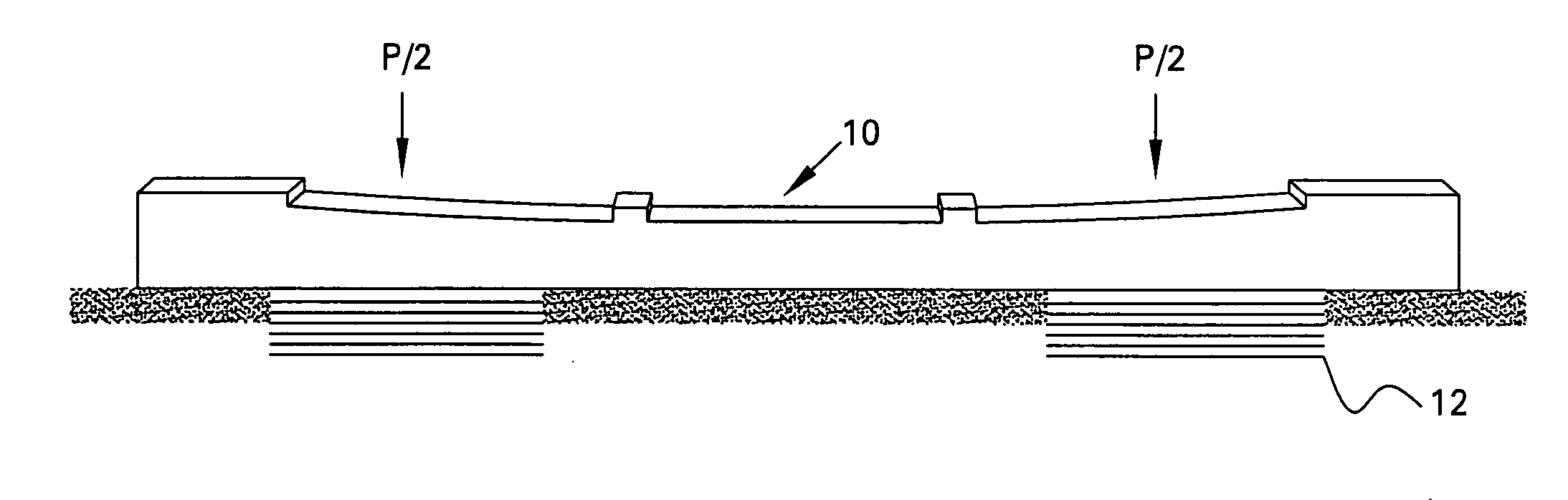
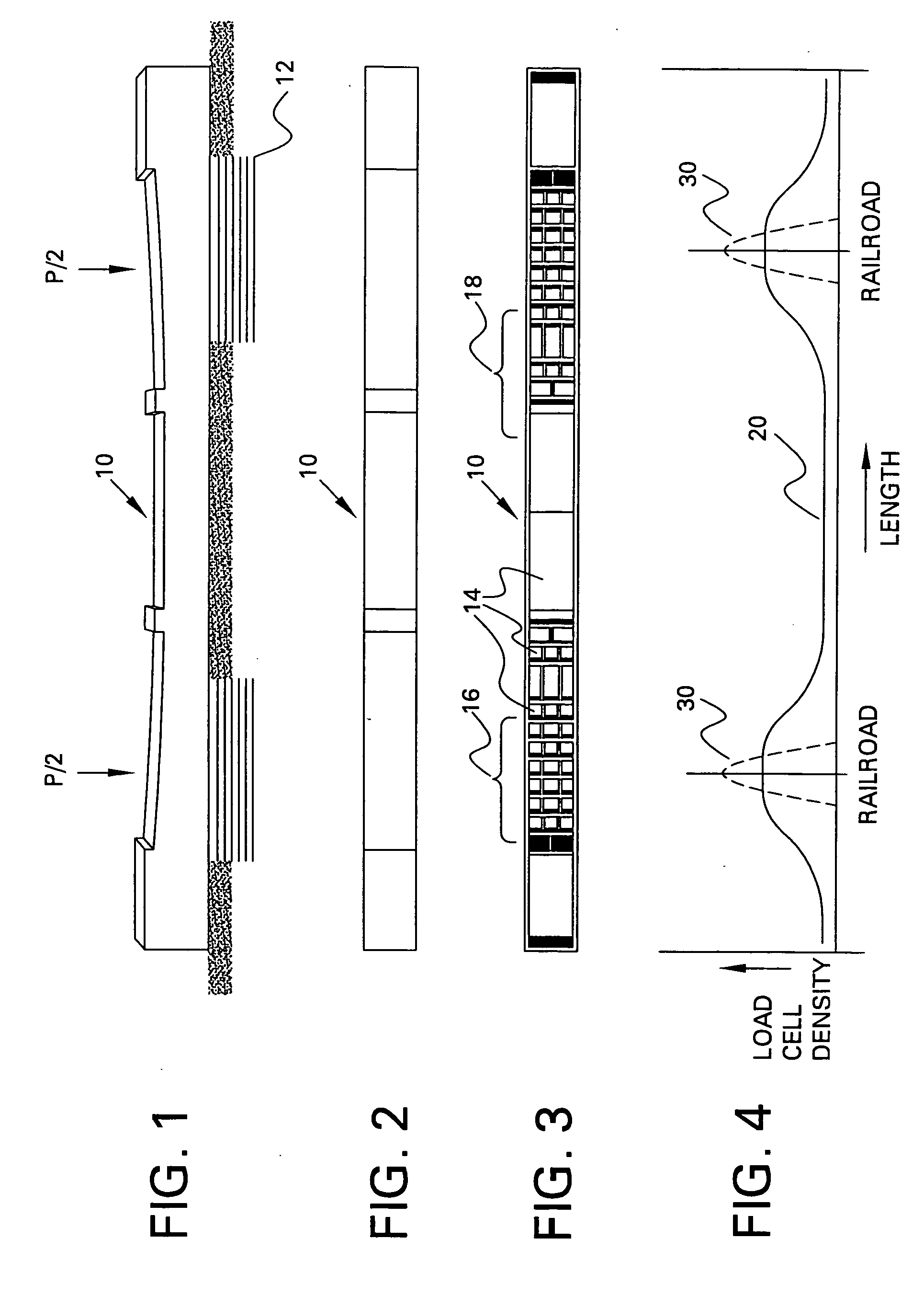
[0013] As noted, the present invention provides a load bearing structure for bearing a load. FIGS. 1-3 illustrate such a load bearing structure, for example, a railway sleeper 10 in accordance with one embodiment of the invention. The railway sleeper 10 holds and supports the rails, bearing a load P at localized zones in the railway sleeper, illustrated in FIG. 1 as equally distributed (P / 2 for each rail). The load P typically represents the load of railway vehicles imparted to the sleeper 10, typically through two rails (not shown). The railway sleeper 10 may be supported by girders 12 as shown, or other alternate supports such as those employed in ballast tracks, or other alternate supports such as those employed in ballastless tracks may be used. Critical parameters for railway sleeper performance include load bearing capacity or bearing stiffness, and dimensional stability or gauge maintenance. Importantly, vibration absorption characteristics of the railroad sleeper 10 translat...


PUM


Abstract

A load bearing structure configured to bear a load, the structure comprising a multiple cells. The load bearing structure has a length, a center, and a cell density, which varies at least along the length of the load bearing structure, which weighs at least 6 kg.

Description

BACKGROUND [0001] This invention relates generally to load bearing structures, and specifically, to efficient load bearing structures and methods for manufacturing the same. [0002] Load bearing structures such as railway ties or railway sleepers serve to transfer the rail loading from the wheel load, which is around 500 kN, to support the structure of the train and the railroad base, to facilitate in gauge maintenance, and to absorb vibrations imparted to the railway tracks, among other functions. Popular conventional materials for railway sleepers include concrete, steel and wood. Concrete is typically a very rigid material and therefore has poor shock absorption characteristics, while steel also suffers from poor vibration absorption characteristics, while use of wood is increasingly being discouraged because it results in depletion of natural resources. In fact, in many countries, policies discontinuing the use of wooden sleepers have been affected. Accordingly, there is a need i...

Claims


Application Information

Patent Timeline
Patent Type & Authority Applications(United States)
IPC IPC(8): E01B3/00
CPCE01B3/44
Inventor THIAGARAJAN, CHINNIAHVENKATESHA, NARAYANASWAMY
Owner GENERAL ELECTRIC CO
Why Eureka
Try Eureka