Radial cell ceramic honeycomb structure

a ceramic honeycomb and radial cell technology, applied in the field of ceramic honeycomb structures, can solve the problems of unacceptably high cell density, unacceptably high pressure drop across the honeycomb structure, and difficult structure, if not impossible to manufacture, and achieve the effect of removing stresses

Inactive Publication Date: 2009-08-18
CORNING INC
View PDF19 Cites 26 Cited by
  • Summary
  • Abstract
  • Description
  • Claims
  • Application Information

AI Technical Summary

Benefits of technology

[0008]Generally speaking, the invention is a radial cell ceramic honeycomb structure that solves or at least ameliorates all of the aforementioned problems. To this end, the ceramic honeycomb structure comprises a plurality of interconnected walls that define a plurality of cells of a honeycomb network having a central axis across its cross section, including radial webs of varying length that diverge from one another in a radial direction away from said central axis, and at least two tangential webs arranged around the central axis wherein at least some of the radial webs extend substantially the length between the central axis and the periphery of the network. The honeycomb network may be cylindrical in shape and covered by a tubular outer skin and each of the radial webs that extends to the periphery of the network may have an outer end that joins an inner edge of the outer skin at a substantially orthogonal orientation. In such a case, the radial webs diverge from a centroid located in the center of the cross section of the network. Alternatively, the honeycomb structure may have an elliptical oval or “race track” cross section, such that the radial webs diverge from a central axis. In such a case, the radial webs will join an inner edge of the skin in either an orthogonal or substantially orthogonal orientation. The orthogonal joints between the radial webs and the inner edge of the outer skin eliminates the stresses associated with prior art honeycomb structures caused by an oblique orientation of some of the web walls that join the inner edge of the outer skin in square, hexagonal, or other polygonal cell designs. The provision of at least some radial webs that extend substantially the length of the radius of the network renders the resulting structure stronger than designs utilizing short radial webs in imbricated patterns.
[0009]To avoid a disadvantageously high density of cells toward the centroid of the structure, only some of the radial webs extend from the centroid to the inner edge of the outer skin. The number of radial webs changes at selected radial distances between the outer skin and the centroid such that a selected average cell density in selected annular portions of the structure is substantially maintained. These selected radial distances correspond to transition zones, and each transition zone is defined by one of the tangential webs. The tangential webs are located along the selected radial distances where the number of radial webs is reduced, for example by half or ⅓, ¼, etc. Preferably, the transition webs are made stronger than the balance of the tangential webs in order to reduce the stresses in this region of the ceramic honeycomb structure. The number of radial webs may decrease in the direction toward the centroid in order to maintain a desired average density of cells along the radius. Alternatively, the number of radial webs may decrease in the outer periphery of the network such that larger cells are formed near the periphery to promote the flow of exhaust gas in this region.

Problems solved by technology

Unfortunately, the applicants have found that all of these designs have shortcomings.
While the “wagon wheel” design has been found to ameliorate the stress problem between the cell webs and the outer skin, it tends to transfer these stresses to the interface between the outer edges of the cell matrix and the inner edge of the cylindrical wall that forms the inner wall of the ring of radial cells.
While the second radial design employing radius-length walls avoids the stress or displacement problem associated with the “wagon wheel” design, it inherently creates an unacceptably high cell density near the center of the cell matrix, where the radial webs simultaneously converge.
This, in turn, generates an unacceptably high pressure drop across the honeycomb structure.
Additionally, such a structure is difficult, if not impossible to manufacture via conventional extrusion techniques, as the convergence of the web walls at the center of the matrix creates disparities in the flow rate of extruded ceramic material that in turn distort or weaken the final structure.
While the imbricated radial cell design solves the aforementioned high cell density and manufacturing problems, it is unacceptably weaker in its interior than conventional designs using square or hexagonal cells.

Method used


Image

  • Radial cell ceramic honeycomb structure
  • Radial cell ceramic honeycomb structure
  • Radial cell ceramic honeycomb structure

Examples


embodiment 60

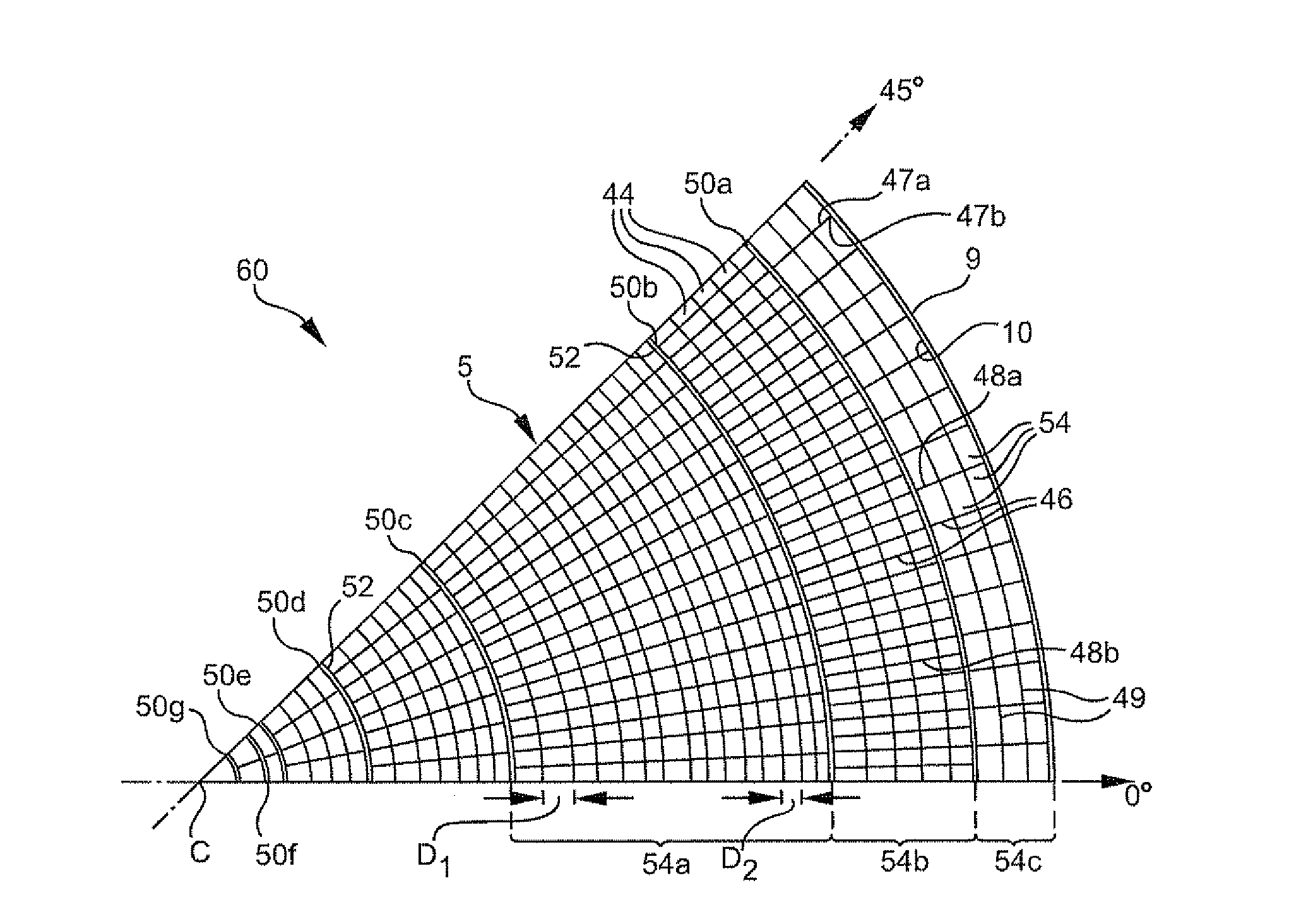
[0027]FIG. 4 illustrates an octant section of an alternate embodiment of the invention. This embodiment is in all respects identical to the embodiment described with respect to FIG. 3, with the exception that every other radial web 46 has been removed from the network 5 in the most peripheral zone 54c, such that the resulting radial cells 54 are twice as large as the balance of the radial cells 44 in the network 5. Hence, in this embodiment, the number of radial webs 46 actually decreases in the radial direction toward the outer skin 9, in contrast to the FIG. 3 embodiment wherein the number of radial webs 46 increases at all points along the radius toward the outer skin 9. The reduction of radial webs 46 in the outermost peripheral portion 54c promotes a larger flow of exhaust gases toward the periphery of the alternate embodiment 60, which thereby reduces the heat gradient across the radius of the ceramic substrate 60 in order to reduce thermally-induced stresses which can sometim...

embodiment 40

[0030]FIG. 6 is a bar graph illustrating the percentage improvement in stress of the FIG. 3 embodiment 40 over the ceramic substrate 1 illustrated in FIGS. 1A and 1B. Here, it can be seen that the average stresses generated as a result of radial tension, radial compression, down-heat up load, and cool down thermal loading are substantially less (are improved) for the inventive ceramic honeycomb illustrated in FIG. 3 versus the prior art illustrated in FIGS. 1A and 1B. In particular, the invention exhibited a large average decrease in maximum stress over its 360° circumference, with greater than 20% improvement in all categories.

[0031]In all cases of comparative peripheral stresses generated by tension, compression, heat up and cool down thermal load, the stresses generated within the inventive structures is highly uniform between 0 degrees and 45 degrees. By contrast, the peripheral stresses generated within the prior art structure 1 oscillate around the circumference of the structu...


PUM

PropertyMeasurementUnit
temperatureaaaaaaaaaa

Abstract

A radial cell ceramic honeycomb structure is provided that is particularly adapted for use as a catalytic carrier or a particulate filter in an automotive or diesel exhaust system. The honeycomb structure includes a network of interconnected webs having a central axis. The network of webs includes radial webs of varying lengths, only some of which substantially extend the entire radial length of the network, and tangential webs that intersect to define rings of gas-conducting radial cells, and a rounded outer skin that surrounds the cells formed by the interconnected webs. The radial webs extending to the periphery of the network join an inner edge of the outer skin in a substantially orthogonal orientation to reduce thermally generated stresses and to increase strength of the resulting structure. The number of radial webs in the network changes along the radial length at transition zones that are defined by one of the tangential webs such that a desired cell density is achieved across the network.

Description

FIELD OF THE INVENTION[0001]This invention generally relates to ceramic honeycomb structures of the type used in automotive or diesel exhaust systems, and is specifically concerned with honeycomb structures having cells formed from interconnected radial and tangential web walls.BACKGROUND OF THE INVENTION[0002]Ceramic honeycomb structures are known in the prior art. Such structures generally comprise a plurality of interconnected web walls that form a matrix of gas-conducting cells which are typically square or hexagonal in shape, and a cylindrical outer skin surrounding the cell matrix. The outer edges of the matrix of web walls is integrally joined to the inner edge of the outer skin to form a single, unitary structure, which is usually cylindrical in shape.[0003]Such ceramic honeycomb structures find particular application as either particulate filters in diesel exhaust systems, or as catalyst substrates for automobile exhaust systems. Hence these structures have an inlet end for...

Claims


Application Information

Patent Timeline
Patent Type & Authority Patents(United States)
IPC IPC(8): B32B3/12B01D46/00B32B3/20B32B3/26B28B11/16B29C47/00
CPCB01D46/0063B01D46/2455B01D46/247B01D46/2474C04B35/185C04B35/195C04B35/478C04B35/565C04B38/0009F01N3/0222B01D46/2451Y10T428/24157B01D46/2466B01D2279/30C04B2111/00793F01N2260/10F01N2330/06F01N2330/48Y10T428/24744Y10T428/24149Y02T10/20Y10T428/249953Y02T10/12B01D46/84B01D46/2484B01D46/2482B01D46/2496
Inventor ANIOLEK, KENNETH WILLIAMBEALL, DOUGLAS MUNROEJAIN, PRIYANK PARASMILLER, KENNETH RICHARDNICKERSON, SETH THOMASSTEPHENS, II, ALAN THOMAS
Owner CORNING INC
Why Eureka
Try Eureka