Hand tool for dentistry and dental prosthetics

a technology for dental prosthetics and hand tools, applied in dental tools, medical science, dentistry, etc., can solve the problems of inadvertent change of the difficulty of adjusting the position of the object, etc., and achieve the effect of rapid and simple clamping or release of the object, and rapid change of the diameter of the cylindrical recess

Inactive Publication Date: 2006-06-22
STRAUMANN HLDG AG
View PDF27 Cites 33 Cited by
  • Summary
  • Abstract
  • Description
  • Claims
  • Application Information

AI Technical Summary

Benefits of technology

[0015] In the embodiment wherein the actuating device includes a sliding sleeve movable in the direction of the main axis, it is possible to cause a more rapid change in the diameter of the cylindrical recess in the clamping area of the collet element, and consequently, a more rapid clamping or release of the object, than is possible with a rotational movement about the main axis. The rotary knob can then be used to preset the resilient clamping area of the collet element to a desired diameter of the object. Accordingly, the object is clamped or released simply through actuation of the sliding sleeve.
[0016] In another embodiment, longitudinal displacement of a push button in the end area of the grip part permits rapid and simple clamping or release of the object.
[0017] One or both of the spring element and the further spring element may comprise a helical compression spring. The use of a helical compression spring permits a simple, compact and inexpensive way of exerting a spring force in a limited space.

Problems solved by technology

Since the existing hand tool is designed for working a rotationally symmetrical object, handling problems may arise if it is used on an object which is not rotationally symmetrical.
The position of the object may inadvertently change during the clamping procedure.

Method used


Image

  • Hand tool for dentistry and dental prosthetics
  • Hand tool for dentistry and dental prosthetics
  • Hand tool for dentistry and dental prosthetics

Examples


first embodiment

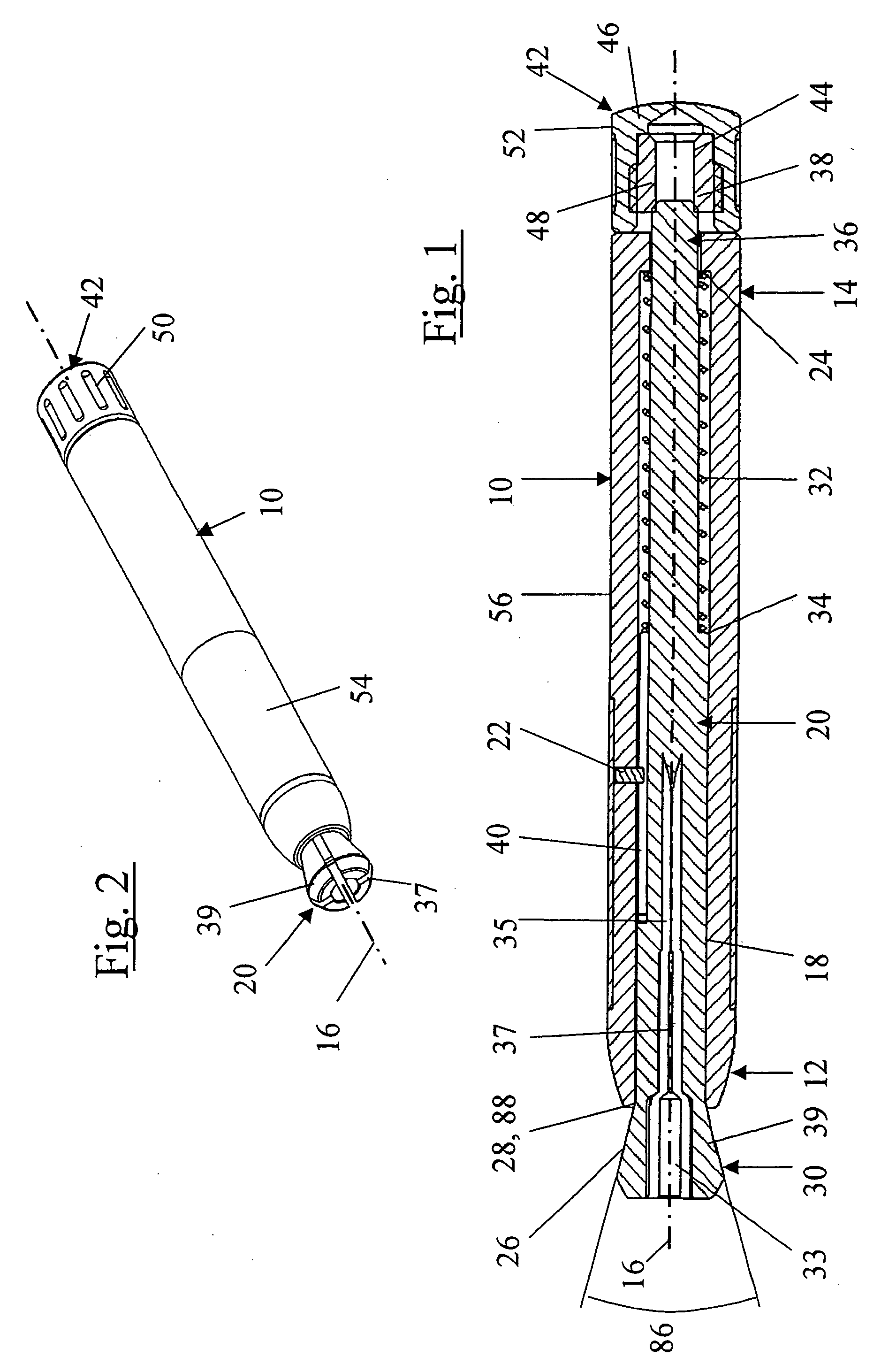
[0028]FIG. 1 and FIG. 2 show a hand tool according to the invention in longitudinal section. A one-piece grip part 10 with a substantially circular cross section has a front end area 12 and a rear end area 14. The circular cross section defines a main axis 16. In the outer front end area 12, the cylindrical grip part 10 is rounded. For simplified and safe handling of the hand tool by the user, a rubber anti-slip element 54 in the form of a sleeve is applied on the circumferential area 56 and is arranged in that half of the hand tool directed toward the front end area 12.

[0029] In the same half of the hand tool, a pin-shaped guide element 22 in the form of a dowel pin is provided in an opening in the grip part 10 arranged radially with respect to the main axis 16, and this guide element is connected fixedly to the grip part 10.

[0030] The interior of the circular cross section of the one-piece grip part 10 is designed as a receiving recess 18 for a collet element 20. In the rear end ...

third embodiment

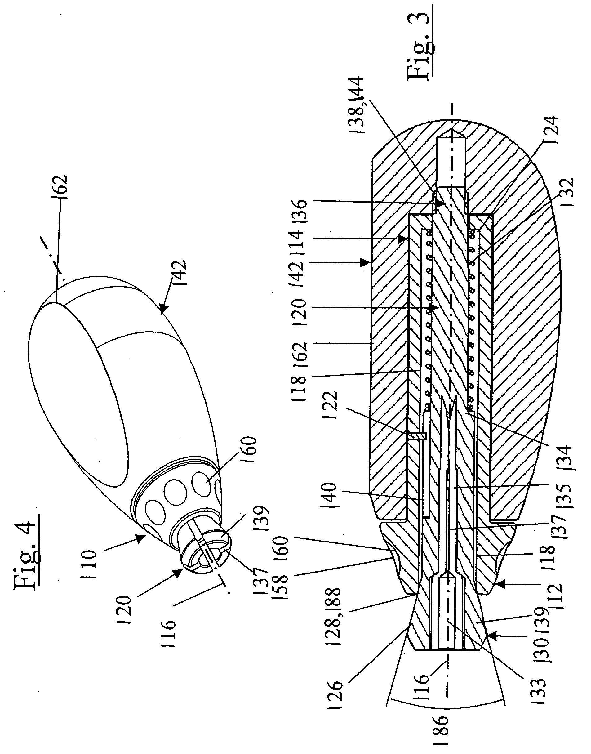
[0055] Similarly to the third embodiment, the push-button recess 374 serves to guide the actuating device in the direction of the main axis 316. In contrast to FIG. 3, however, instead of the rotary knob 142, the push button 372 is guided axially.

[0056] The push button 372 has an internal thread 376 oriented toward the front end area 312. This internal thread 376 is screwed onto the external thread 338 of the collet element 320. Moreover, at its free end, the push button 372 has a press surface 378 for actuating it.

[0057] The spring element 332 in the form of a helical compression spring is arranged in the receiving recess 318. In contrast to the first embodiment, it bears at one end on the shoulder 324 of the grip part 310 and at the other end on the shoulder 380 of the push button 372 and engages round the collet element 320 and also round the push button 372 in the direction of the main axis 316.

[0058] In FIG. 7, the collet element 320 is shown in the position in which the resi...


PUM


Abstract

A hand tool for dentistry and/or dental prosthetics, having a grip part which defines a main axis and, in the direction of the main axis, comprises a front end area and a rear end area. The grip part has, in the front end area, an open receiving recess in which the collet element is arranged with an adjustable receiving diameter for receiving an object. The receiving diameter of the collet element can be modified by way of an actuating device. The collet element can be secured against rotation in the grip part.

Description

FIELD OF THE INVENTION [0001] The present invention relates to a hand tool for dentistry and / or dental prosthetics. BACKGROUND [0002] Institut Straumann AG (Basel, Switzerland) markets a hand tool for dentistry and / or dental prosthetics which is made up of a cylindrical grip part, a collet element and an actuating device, the grip part having, in the front end area, an external thread and also a receiving recess in the form of a blind bore along the main axis of the cylindrical grip part. The collet element is partially engaged in this receiving recess and is used to receive a rotationally symmetrical object that is to be worked (e.g., rotated during use). At its front end area projecting beyond the grip part, the collet element has an external cone envelope surface tapering toward the free end. The actuating device in the form of a cap-like union nut, which can be screwed on over the external thread in the front end area of the grip part, has, inside a passage, a bearing surface ac...

Claims


Application Information

Patent Timeline
Patent Type & Authority Applications(United States)
IPC IPC(8): B25B9/00
CPCA61C3/10
Inventor MAURER, PHILIPPTAORMINA, MATTEOLINDER, ANDREAS
Owner STRAUMANN HLDG AG
Why Eureka
Try Eureka