Fan

a fan and fan hub technology, applied in the field of fans, can solve the problems of prone to fall off of the fan hub, and achieve the effect of greatly enhancing the connection strength between the shaft and the fan hub

Inactive Publication Date: 2006-06-22
DELTA ELECTRONICS INC
View PDF4 Cites 12 Cited by
  • Summary
  • Abstract
  • Description
  • Claims
  • Application Information

AI Technical Summary

Benefits of technology

[0008] An object of the invention is to provide a fan capable of enhancing the connection strength between a fan hub and a shaft.
[0010] Through the invention, since the fan hub is formed with an extrusion protruding from its outer planar surface, and the shaft is elongated and protrudes from the top planar surface of the fan hub or the bottom surface of the fan base, an additional contact area between the shaft and the fan hub is provided when the extension portion of the shaft is enclosed by and in close connection with the extrusion of the fan hub. Thus, the connection strength between the shaft and the fan hub is greatly enhanced.

Problems solved by technology

A fan hub is liable to fall off if the connection strength between the fan hub and the shaft is not high enough to withstand the continuous vibrations during long periods of operation.

Method used


Image

  • Fan
  • Fan
  • Fan

Examples


Embodiment Construction

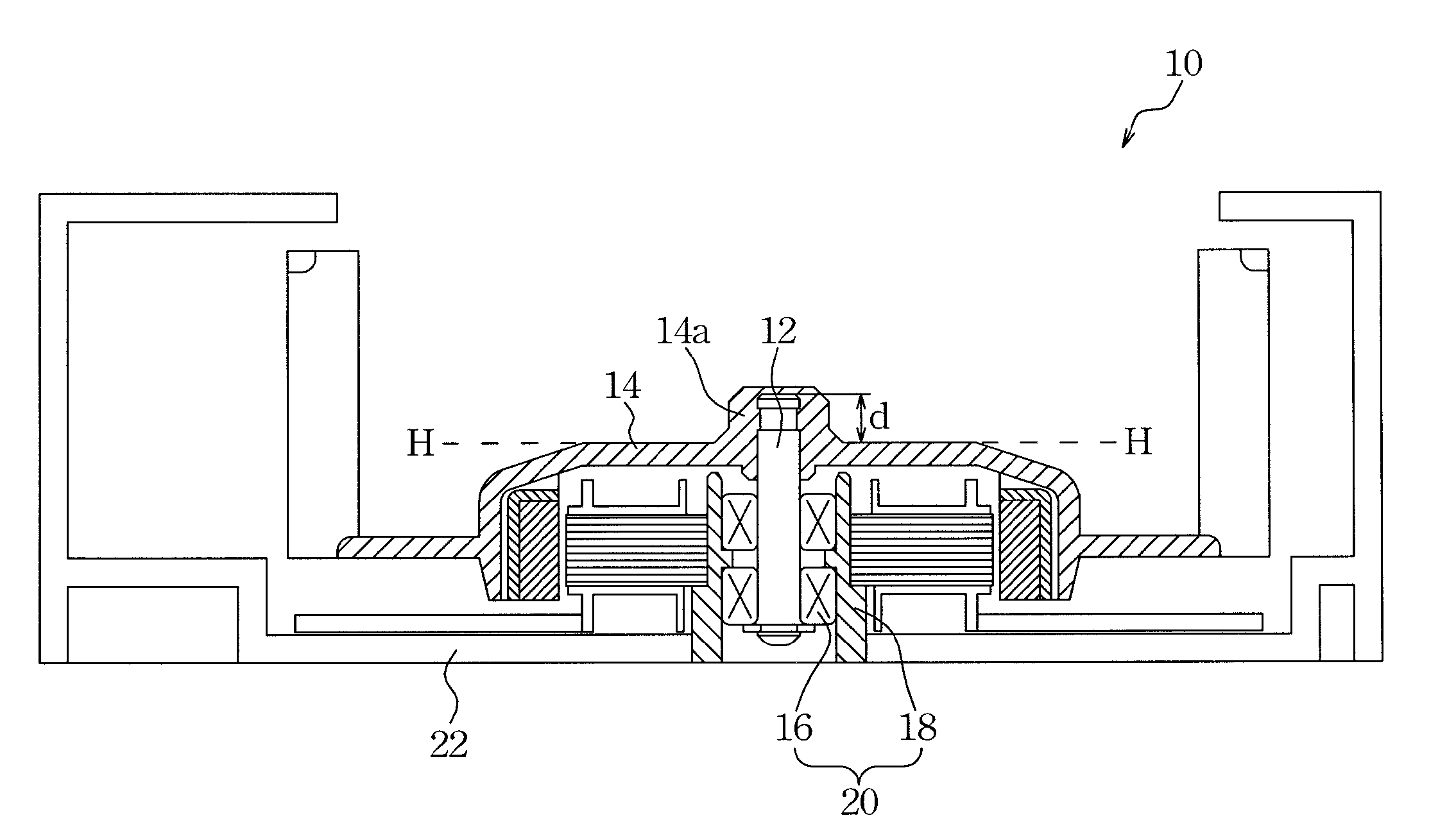
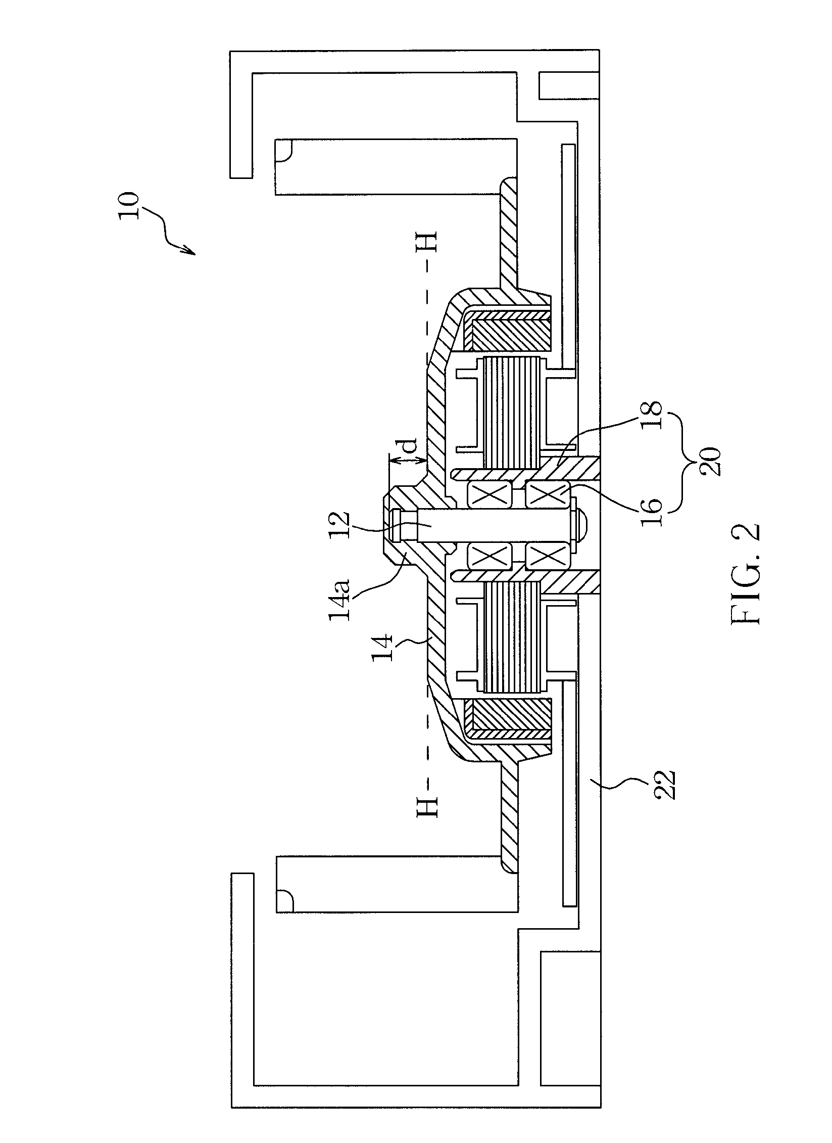
[0018] Referring to FIG. 2, according to an embodiment of the invention, a fan 10 includes a shaft 12 having a first end connected to a fan hub 14 and a second end fit into a bearing assembly 20. The bearing assembly 20 is mounted on a fan base 22 and includes a bearing 16 and a bearing seat 18 for accommodating and positioning the bearing 16.

[0019] In this embodiment, the fan hub 14 is formed with an extrusion 14a protruding from a top planar surface H of the fan hub 14 in its central location. The shaft 12 is also elongated to protrude upwards from the top planar surface H of the fan hub 14 to form an extension portion with a length d in the axial direction of the fan 10. Thereby, the extension portion of the shaft 12 is enclosed by and in close connection with the extrusion 14a of the fan hub 14. Specifically, the height of the extension portion of the shaft 12 is approximately equal to the height of extrusion 14a of the fan hub 14.

[0020] It should be understood that the extrus...


PUM


Abstract

A fan includes a fan base, a bearing assembly, a fan hub and a shaft. The fan hub is formed with an extrusion protruding from its top planar surface, and the shaft is fit into the bearing assembly and connected to the fan hub. The shaft has one end protruding from the top planar surface of the fan hub to form an extension portion, and the extension portion of the shaft is enclosed by and in close connection with the extrusion of the fan hub.

Description

CROSS-REFERRENCE TO RELATED APPLICATIONS [0001] This application is a continuation-in-part of U.S. application Ser. No. 10 / 799,420, filed Mar. 12, 2004, which claims priority to Taiwan application 92206497, filed Apr. 23, 2003, now pending.BACKGROUND OF THE INVENTION [0002] (a) Field of the Invention [0003] The invention relates to a fan and, more particularly, to a fan capable of enhancing the connection strength between a fan hub and a shaft. [0004] (b) Description of the Related Art [0005] A fan hub is liable to fall off if the connection strength between the fan hub and the shaft is not high enough to withstand the continuous vibrations during long periods of operation. [0006] A cross-sectional view of a conventional fan 100 is shown in FIG. 1. Referring to FIG. 1, when the shaft 102 is connected to the fan hub 104, the area of the contact surface P between the shaft 102 and the fan hub 104 determines the magnitude of the connection strength between them; more specifically, the ...

Claims


Application Information

Patent Timeline
Patent Type & Authority Applications(United States)
IPC IPC(8): H02K7/00H02K5/00H02K11/00
CPCF04D29/263H02K5/163H02K7/085
Inventor CHIU, YUNG-YUCHANG, SHUN-CHENLIN, KUO-CHENGHUANG, WEN-SHI
Owner DELTA ELECTRONICS INC
Why Eureka
Try Eureka