
Vehicle headlamp

a headlamp and headlamp technology, applied in the field of headlamps, can solve the problems of affecting the safety of road users, and affecting the operation of vehicles, so as to prevent glare, not dazzle road users, and improve visibility

Inactive Publication Date: 2006-06-22
KOITO MFG CO LTD
View PDF8 Cites 5 Cited by
  • Summary
  • Abstract
  • Description
  • Claims
  • Application Information

AI Technical Summary

Benefits of technology

[0026] Thus, when an abnormality occurs in the first actuator or the second actuator, a measure for preventing glare is taken in a manner that the abnormality is directly detected without using the communication unit thereby to perform a processing according to a portion where the abnormality or a failure occurs.
[0027] Thus, in the case where the control device erroneously determines that an abnormality occurs at the first a controller despite that an abnormality occurs at the communication system communicating with the controller, the duplicated directional adjustment by the first and second actuators can be prevented.
[0030] In this manner, it is possible to suitably adjust the irradiation direction and the lighting state on a condition that the current state as well as a portion where an abnormality or a failure occurs is sufficiently grasped, thereby performing the irradiation control so as not to dazzle road users.
[0031] According to one or more embodiments of the present invention, a suitable measure can be made in a case where an abnormality relating to the plurality of actuators for controlling the irradiation direction occurs or a failure of the controller or the communication system with the controller occurs, so that a sufficient measure for preventing glare from being applied to road users can be taken and the degradation of visibility in the forward direction of own vehicle due to the excessive irradiation direction adjustment can be prevented.
[0032] Further, in accordance with one or more embodiments of the present invention, a driving unit formed by integrating the first and second actuators is provided within the lamp body. Therefore, it is effective to secure the arrangement space, facilitate the attachment procedure, miniaturize the size and reduce the cost etc.
[0034] It is particularly effective so as to prevent glare due to a light beam directed to the opposite lane when this control is performed in a case where the occurrence of an abnormality relating to the first actuator is detected in a state where a light beam is irradiated toward the opposite lane side.

Problems solved by technology

In particular, in the system including the swivel control in the light distribution control at the time of light irradiation of a low beam (or a dipped beam), since there is a difference in the height of a cut-off line between own lane (a lane on an own vehicle side) and an opposite lane, there arises a problem in a situation of being out of the suitable swivel control.
Thus, the running stability may be degraded depending on the circumstances.
As another case, if any failure occurs at a communication line coupling the control device and the respective actuators, there arises a problem of an erroneous operation caused by unexpected swivel control or leveling control.
However, the aforesaid conventional configurations have a problem that a measure in the case that the operations responding to a failure or an abnormality etc. are performed in a duplicated manner is not considered sufficiently.
If such duplicated adjustments are performed excessively, an unsuitable irradiation state may be caused.
In a circumstance where an abnormality or a failure does not necessarily occur individually, it is difficult to avoid the excessive or useless control so long as a measure sufficiently considering the composite operation is not taken.

Method used


Image

  • Vehicle headlamp
  • Vehicle headlamp
  • Vehicle headlamp

Examples


Embodiment Construction

[0047] Embodiments of the invention will be described with reference to the accompanying drawings.

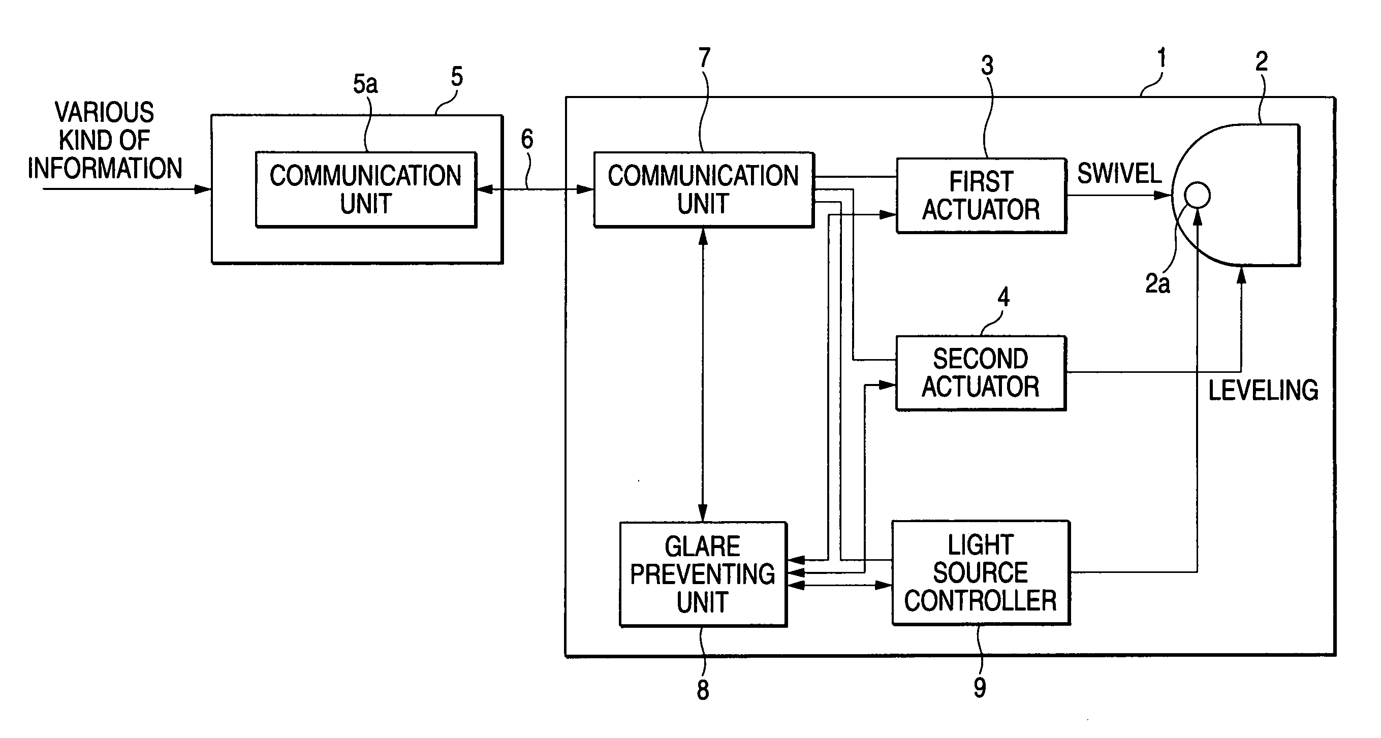
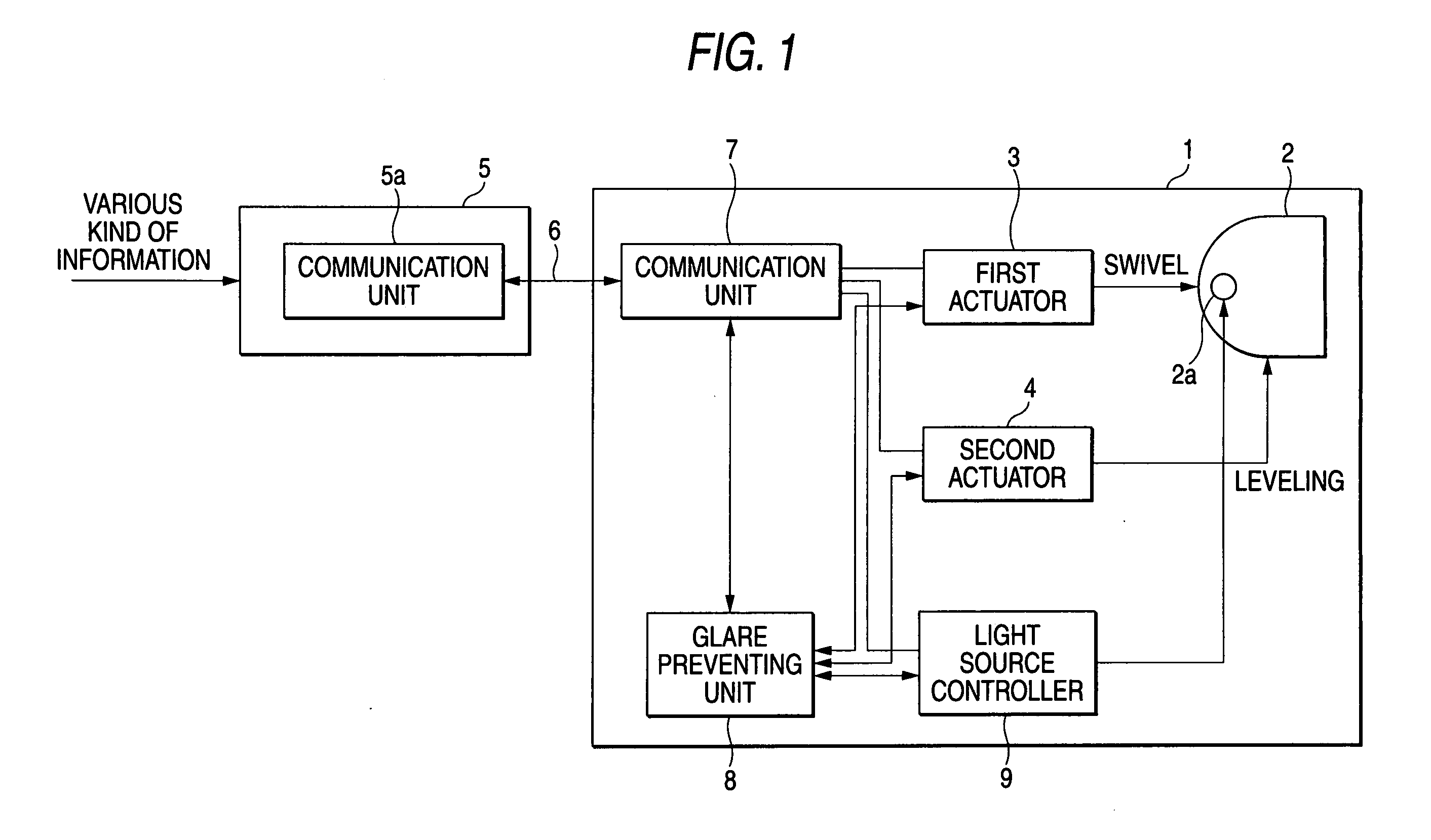
[0048]FIG. 1 is a diagram exemplarily showing the basic configuration of a headlamp for a vehicle according to the invention.

[0049] A vehicle headlamp 1 includes a lamp unit 2 capable of performing the swivel control and the leveling control when applied to a headlamp for a vehicle, for example. That is, the lamp unit 2 is controlled in its irradiation direction in accordance with the traveling condition of a vehicle. The lamp unit 2 includes a light source 2a using a bulb or a discharge lamp etc. and an optical system of irradiating a light beam in the forward direction by using a reflection mirror and a lens member.

[0050] There are following modes as an actuator for performing the swivel control and the leveling control.

[0051] A configuration mode using a two-axis actuator having both the swivel function and the leveling function; and

[0052] a configuration mode separately provide...


PUM


Abstract

A vehicle headlamp is provided with a lamp unit, a first actuator for controlling the irradiation direction within the horizontal plane, a second actuator for controlling the irradiation direction within the vertical plane. A communication unit transmits and receives a signal between the actuators and a controller provided outside of the lamp body via a communication line. A glare preventing unit detects an abnormality or a failure of the actuators, the controller, and the communication line, without using the communication unit. The irradiation direction or the lighting state is changed in accordance with a portion where the abnormality or the failure.

Description

[0001] The present application claims foreign priority based on Japanese Patent Application No. P.2004-355721, filed on Dec. 8, 2004, the contents of which are incorporated herein by reference. BACKGROUND OF THE INVENTION [0002] 1. Field of the Invention [0003] The present invention relates to a vehicle headlamp capable of controlling the irradiation angle in accordance with a traveling condition of the vehicle, and to a technique for preventing glare in order to prevent a phenomenon that the irradiation direction is fixed to a not-intended direction due to an occurrence of an abnormality or a failure and so a dazzling light beam is irradiated to road users such as drivers of oncoming vehicles or walkers. [0004] 2. Related Art [0005] An adaptive front-lighting system (AFS) capable of controlling light distribution in accordance with a traveling condition of a vehicle is arranged to, in order to perform variable control of a light distribution, obtain steering detection information f...

Claims


Application Information

Patent Timeline
Patent Type & Authority Applications(United States)
IPC IPC(8): G01B13/18B60Q1/00G02B27/00
CPCB60Q1/10B60Q1/12B60Q2300/146
Inventor HAYAMI, TOSHIHISA
Owner KOITO MFG CO LTD
Learn More