Optical recording using a waveguide structure and a phase change medium

a waveguide structure and phase change technology, applied in the field of optical recording using a waveguide structure and phase change medium, can solve the problems that sub-diffraction-limit marks cannot be detected on a storage medium, and requires substantial effort from the servo system

Inactive Publication Date: 2006-06-22
SEAGATE TECH LLC
View PDF40 Cites 29 Cited by
  • Summary
  • Abstract
  • Description
  • Claims
  • Application Information

AI Technical Summary

Problems solved by technology

Using optical far field techniques sub-diffraction-limit marks cannot be detected on a storage medium.
In addition, keeping the focal point at the right position with respect to

Method used


Image

  • Optical recording using a waveguide structure and a phase change medium
  • Optical recording using a waveguide structure and a phase change medium
  • Optical recording using a waveguide structure and a phase change medium

Examples


Embodiment Construction

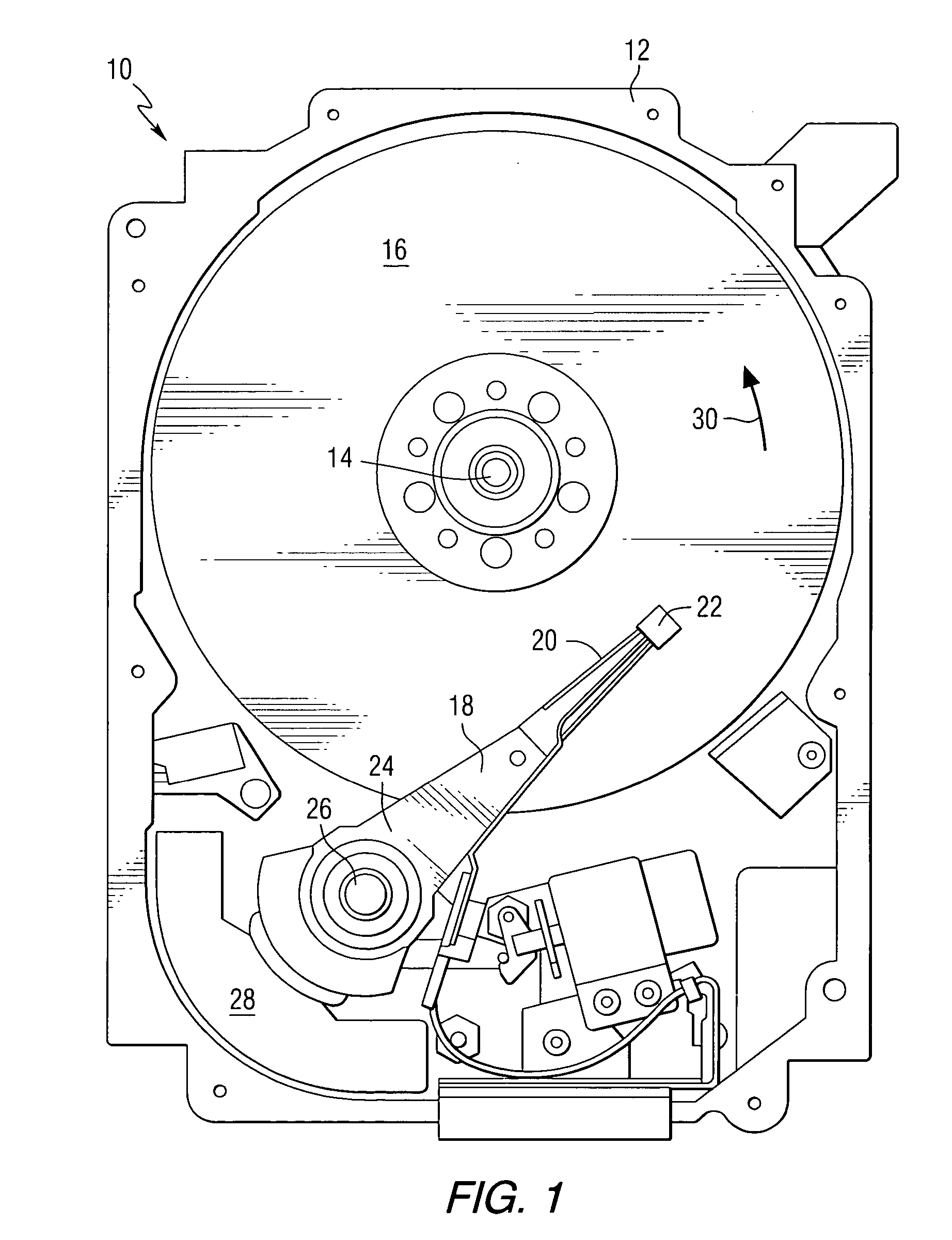
[0021] Referring to the drawings, FIG. 1 is a pictorial representation of a head disc assembly portion of a disc drive 10 including a recording head that can be constructed in accordance with this invention. The disc drive includes a housing 12 (with the upper portion removed and the lower portion visible in this view) sized and configured to contain the various components of the disc drive. A spindle motor 14 is provided for rotating at least one data storage medium 16 within the housing. At least one arm 18 is contained within the housing 12, with each arm 18 having a first end 20 with a recording and / or reading head or slider 22, and a second end 24 pivotally mounted on a shaft by a bearing 26. An actuator motor 28 is located at the arm's second end 24, for pivoting the arm 18 about a pivot point to position the head 22 over a desired sector of the disc 16. The actuator motor 28 is regulated by a controller that is not shown in this view and is well-known in the art. The storage ...


PUM


Abstract

An apparatus comprises a slider having an air bearing surface, a first waveguide for directing electromagnetic radiation to a focal point adjacent to the air bearing surface, a storage medium position adjacent to the air bearing surface, a detector for detecting electromagnetic radiation reflected from the storage medium, and a structure positioned adjacent to the focal point for collecting the reflected electromagnetic radiation and for transmitted the reflected electromagnetic radiation toward the detector.

Description

STATEMENT REGARDING FEDERALLY SPONSORED RESEARCH OR DEVELOPMENT [0001] This invention was made with United States Government support under Agreement No. 70NANB1H3056 awarded by the National Institute of Standards and Technology (NIST). The United States Government has certain rights in the invention.FIELD OF THE INVENTION [0002] This invention relates to data storage devices and more particularly to optical storage devices that utilize phase change storage media. BACKGROUND OF THE INVENTION [0003] Optical data systems rely on a beam of light to write and read information on a storage medium. There is a fundamental constraint—the diffraction limit—on how tightly the beam of light can be focused. This limit is directly related to the wavelength of the light. With a shorter wavelength, a smaller spot of light can be made and hence, more bits can be stored on a given area. The resolution limit is given by Abbe's equation: Resolution=(Wavelength*0.61) / (Numerical Aperture). [0004] Reducti...

Claims


Application Information

Patent Timeline
IPC IPC(8): G11B7/00G11B7/12G11B7/135
CPCG01N21/9506G11B5/4555G11B7/00375G11B7/1203G11B7/1206G11B7/1353G11B7/1362G11B7/1384G11B7/1387G11B9/04G11B7/122G11B7/124
Inventor BUECHEL, DOROTHEAWELLER, DIETER KLAUSGAGE, EDWARD CHARLESCHALLENER, WILLIAM ALBERTMIHALCEA, CHRISTOPHE DANIEL
Owner SEAGATE TECH LLC
Why Eureka
Try Eureka