Counter device and counting method

Inactive Publication Date: 2006-06-22
KYOCERA DOCUMENT SOLUTIONS INC
View PDF4 Cites 23 Cited by
  • Summary
  • Abstract
  • Description
  • Claims
  • Application Information

AI Technical Summary

Benefits of technology

[0019] According to the invention, the control section turns a bit from high to low by one bit units so as to update the first counter value of the lower counter, and updates the second counter value of the upper counter each time the first counter value by the lower counter comes around. Consequently, an advantage is obtained in that the device load can be reduced, and the reliability of the counter value can be increased, without increasing the memory capacity nor the cos

Problems solved by technology

In this case, it is not guaranteed by the manufacturer.
For example, if several hundred thousand units are counted, several hundred thou

Method used


Image

  • Counter device and counting method
  • Counter device and counting method
  • Counter device and counting method

Examples


first embodiment

[0032] Next, FIG. 2 is a schematic diagram showing the operation of the counter device. In the first embodiment, the counter value is controlled as a complement of 1. Firstly, as an initial setting, all bits of the counter 2 are set to “1” (as shown a top of bit string “111111111” in FIG. 2). After the initial setting, actual counting is performed. That is, the counting operation is performed with respect to the complement of 1. FIG. 2 shows the sate transition of the counter 2 when the counter value is changed from 0 to 15 (from top to bottom). As shown in FIG. 2, a right end value of each bit string, become bit “0”, bit “1”, bit “0”, . . . , in order from the top of bit string to the bottom bit string. By increasing the count, the bit is turned from OFF to ON (from bit “0” to bit “1”) every other time (as shown hatched part in FIG. 2).

[0033] Here, FIG. 3 is a schematic diagram showing the frequency of sector erasures in the counter device according to the first embodiment. As desc...

second embodiment

[0035] Next, a description is second embodiment of the invention with reference to the drawings.

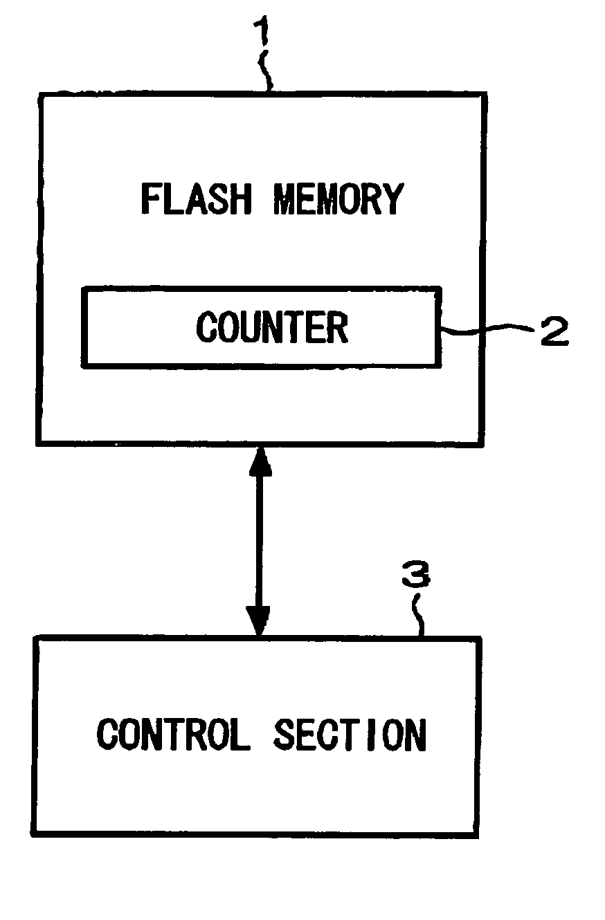
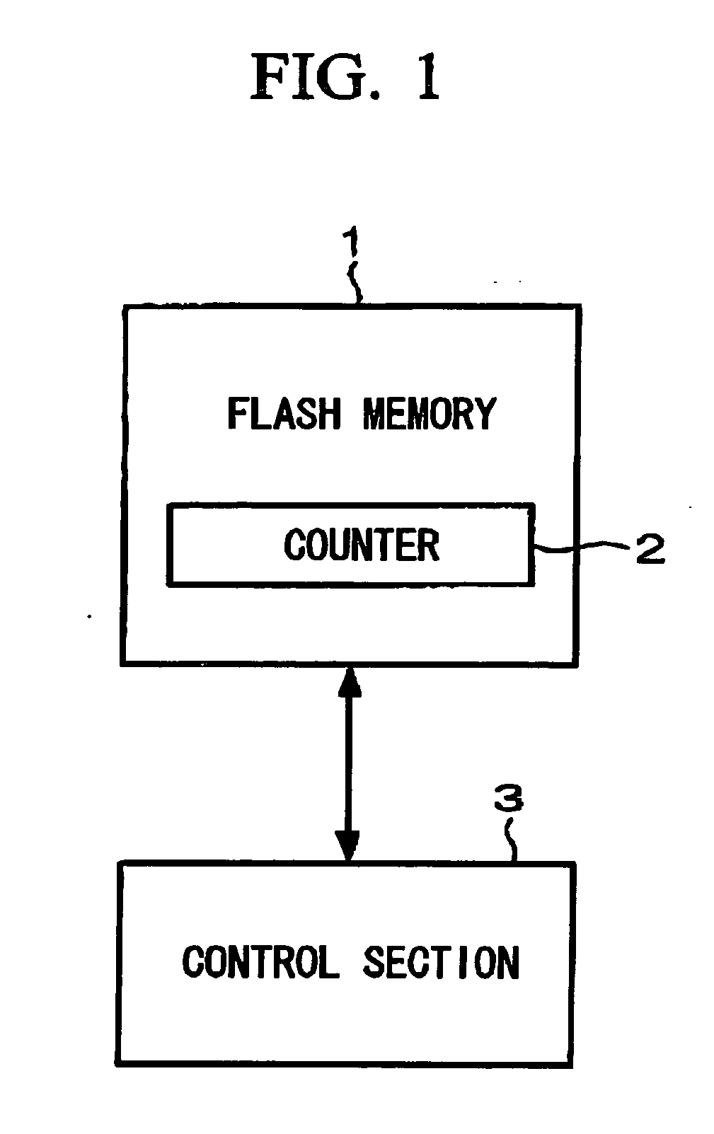
[0036]FIG. 4 is a block diagram showing a counter device of second embodiment of the invention. A flash memory 1 is a non-volatile memory, and has a counter 2. The counter 2 is configured by a predetermined number of bits, and counts the accumulated number of rewritings. A control section 3 controls the writing in and reading out the data of the counter 2. Similarly to a conventional counter, the counter 2 includes, a lower counter 2a which makes one count by turning the bit from ON (“1”) to OFF (“0”) for each one bit unit, and an upper counter 2b which counts the number of resettings each time the lower counter 2a is reset, by a general counting method (as show in FIG. 4). Hereunder, in order to simplify the description, the lower counter 2a is set to 32 bytes (1 byte=8 bits, total 256 bits), and the upper counter 2b is set to 1 byte (8 bits). However, the number of bits is not limited t...


PUM


Abstract

A counter device includes: a rewritable counter having a non-volatile memory which requires sector erasure to once turn all data in a sector into high data, prior to changing low data into high data in respective bits; and a control section updating a counter value of the rewritable count by writing in and reading out the data with respect to the rewritable counter using a complement of 1, and thereby controlling writing in and reading out the data of the rewritable counter.

Description

BACKGROUND OF THE INVENTION [0001] 1. Field of the Invention [0002] The present invention relates to a counter device, and a counting method using a non-volatile memory. [0003] Priority is claimed on Japanese Patent Application No. 2004-351590, filed Dec. 3, 2004, and Japanese Patent Application No. 2004-351591, filed Dec. 3, 2004, the contents of which are incorporated herein by reference. [0004] 2. Description of Related Art [0005] A printer and a copier control a large number of counters by a non-volatile memory (flash memory: registered trademark). The counter counts the number of printed sheets and is also used for accounting purpose. Therefore a high reliability is required. The non-volatile memory the reliability is described as the bits are used more frequently. Therefore, the manufacturer sets a guaranteed number of writings. If the number of writings exceeds the set number, the reliability of the non-volatile memory is remarkably decreased. In this case, it is not guarante...

Claims


Application Information

Patent Timeline
IPC IPC(8): G06M1/00
CPCH03K21/403
Inventor TAKAGI, SEIGO
Owner KYOCERA DOCUMENT SOLUTIONS INC
Why Eureka
Try Eureka