Call center apparatus and functionality in telephony

a call center and functionality technology, applied in the field of intelligent callrouting system, can solve the problems of inability to change the rules arbitrarily, all such systems exhibit common drawbacks,

Inactive Publication Date: 2006-06-22
NEYMAN IGOR +11
View PDF1 Cites 24 Cited by
  • Summary
  • Abstract
  • Description
  • Claims
  • Application Information

AI Technical Summary

Problems solved by technology

In current art, although there are widely varying systems in the art relative to routing rules, all such systems exhibit a common drawback.
Typically such systems, once set up (programmed) to follow certain routing rules and practices, cannot easily vary, and individual users or groups of users, cannot change the rules arbitrarily.

Method used


Image

  • Call center apparatus and functionality in telephony
  • Call center apparatus and functionality in telephony
  • Call center apparatus and functionality in telephony

Examples


Embodiment Construction

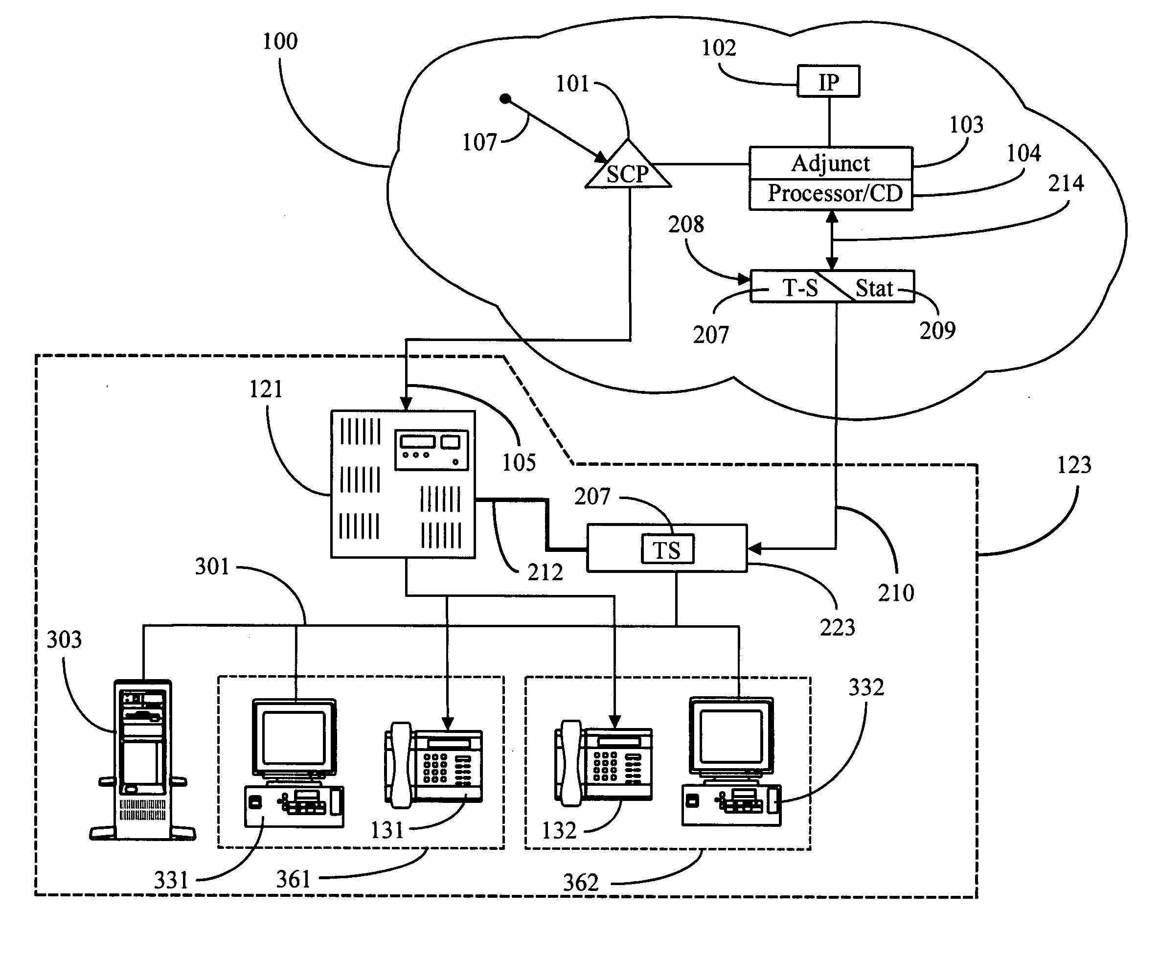
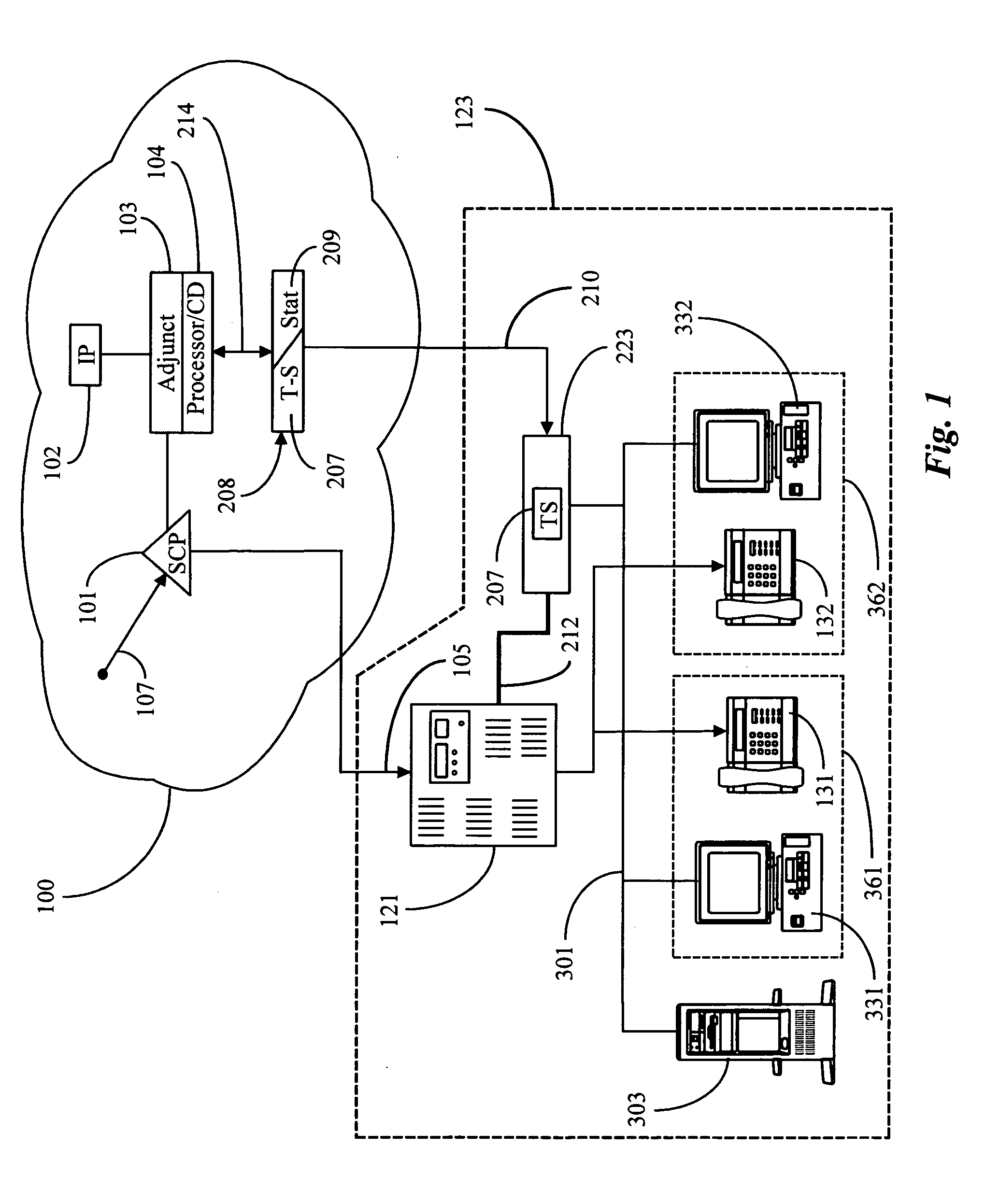
[0023]FIG. 1 is a system diagram of a call-routing system according to a preferred embodiment of the present invention. Dotted lines 123 enclose elements of the system native to a customer's premises (CPE). This equipment in a preferred embodiment comprises a computerized telephony central switch 121 connected by a data link 212 to a processor 223 running an instance of a unique telephony server (T-Server) T-S 207. Switch 121 in conventional art distributes incoming calls (on line 105) to connected telephones, such as telephone 131 at a workstation 361 and telephone 132 at a second workstation 362. In various embodiments of the present invention T-Server 207 running on processor 223 exerts controlling influence on routing of incoming calls, as is described in further detail below.

[0024] In various embodiments of the present invention each workstation (361, 362) has a PC with a video display, such as PC / VDU 331 at workstation 361 and PC / VDU 332 at workstation 362. There will be in m...


PUM


Abstract

A client-server telephone call router system as part of a customer premises system has a client-server router adapted to execute on a telephony switch, such as a public branch exchange (PBX) or other telephony switch, or on a processor connected by CTI link to a telephony switch. The telephony switch or processor executing the router is connected to a local area network (LAN) that also interconnects computer workstations proximate to telephones connected to the telephony switch. Client user interface applications run on the computer workstations, allowing clients to edit routing rules for the router, which has a list of routing rules keyed to users and workstations of the customer premises system. The editing rules are kept by the router in portions dedicated to individual users. With this system a user can edit at a workstation on the LAN his\her own routing rules, and transmit the edits to the client-server router where the rules will be followed to route calls for that user and protocol.

Description

CROSS-REFERENCE TO RELATED DOCUMENTS [0001] The present application is a Continuation-In-Part (CIP) of prior copending patent application Ser. No. 08 / 869,815, which is a CIP of copending application Ser. No. 08 / 802,667, which is a CIP of copending patent application Ser. No. 08 / 797,420. The present application is also a CIP of copending application Ser. No. 08 / 833,340, and of a copending application having an Attorney Docket number P3226, filed Jul. 9, 1997. Titled “Methods in Computer Simulation of Telephony Systems”, for which the USPTO has not, at the time of the present application, returned a S / N.FIELD OF THE INVENTION [0002] The present invention is in the area of telephone call processing and switching, and pertains more particularly to intelligent call-routing systems, and equipment and methods for customizing and Personalizing Routing Rules and Protocol. BACKGROUND OF THE INVENTION [0003] Telephone call processing and switching systems are, at the time of the present patent...

Claims


Application Information

Patent Timeline
Patent Type & Authority Applications(United States)
IPC IPC(8): H04M1/64H04M7/00H04L12/64H04M3/00H04M3/32H04M3/42H04M3/51H04M3/523H04M3/60H04M5/00H04Q3/58
CPCH04M3/323H04M7/00H04M3/42059H04M3/42102H04M3/42127H04M3/42153H04M3/42161H04M3/42221H04M3/5183H04M3/5191H04M3/523H04M3/5235H04M7/006H04M2201/40H04M2201/42H04M2203/408H04M2242/22H04M3/42042H04M1/2473
Inventor NEYMAN, IGORBARSKIY, MICHAILMILOSLAVSKY, ALECBONDARENKE, OLEGISSAYEV, VALERIYPETROV, ANDREIKARPENKO, PAULSMELIK, ALEXVOLGUIN, ALEXANDEROSTAPCHUK, YURILIVSHITS, BORISDADGAR, HAMID
Owner NEYMAN IGOR
Why Eureka
Try Eureka