Fastened assembly body, connector, and hydraulic cylinder unit

a technology for connecting parts and hydraulic cylinders, applied in the direction of rod connections, couplings, servomotors, etc., can solve the problems of preventing space from being saved, and affecting the stability of the connection, and achieve the effect of high versatility

Inactive Publication Date: 2006-06-22
KOGANEI
View PDF12 Cites 37 Cited by
  • Summary
  • Abstract
  • Description
  • Claims
  • Application Information

AI Technical Summary

Benefits of technology

[0020] In the fastening assembly and the fastener of the present invention, the communication groove and the engagement groove having the engagement surface are formed in each of the connection surfaces of the two fastened members, so that the entirety of the fastener can be inserted into their interiors in a state of being opposed to and completely communicating with each other. In this inserted state, since the fastening surfaces of the engaging pieces contact and are engaged respectively with the engagement surfaces, they are not removed from the connection surfaces of the members in the direction orthogonal thereto. Therefore, the two members cannot be separated from each other via the fastener, that is, the two members can obtain a firmly fastened state so that there is nothing protruding from the surfaces thereof. In the two members, the relative arrangements and the positions to be fastened can be arbitrarily and easily set and changed.
[0030] In the fluid pressure cylinder unit of the present invention, since the fluid pressure cylinder and the attachment can be firmly fastened without anything protruding therefrom, the above is the structure suitable for saving the installation space. Concurrently, since the fluid pressure cylinder, guide unit, and spacer block, etc. can be easily and certainly fastened mutually, a cylinder unit of, for example, a single or double guide-attached cylinder, a lifter cylinder, an air chuck, or a double-stroke cylinder can be easily assembled. Further, in the two cylinder tubes, since the relative arrangements and the positions to be fastened can be arbitrarily and easily set and changed, the fastening can be easily obtained by combining an arbitrary fluid pressure cylinder with an arbitrary guide unit.
[0036] In the fluid pressure cylinder unit of the present invention, since the casing of the rodless cylinder and the adjacent attachment can be firmly fastened without anything protruding therefrom, this is suitable for saving the installation space and the rigidity of the rodless cylinder can be enhanced. The attaching position of the fastener to the casing can be arbitrarily set by being moved along the engagement groove. If the attachment is a guide member, the reciprocating body can be moved with higher accuracy by guiding through the guide member the reciprocating body that is driven by the rodless cylinder.
[0044] In the fluid pressure cylinder unit of the present invention, the fluid pressure cylinder employed therein can selectively attach, in accordance with the use application, a rod cover provided with the functional component such as a dust discharge passage, an oil-impregnated bearing, a ball bearing, or an assembly for stroke adjustment to the basic cylinder provided in common as a main body driving unit. Therefore, the structure capable of being applied to various uses and exhibiting high versatility can be attained.

Problems solved by technology

These are large factors for hindering a space from being saved since the space for installing each member is limited depending on recent device downsizing.
However, even if each of the protrusion and the elastic protrusion on each side is inserted into the T-shaped groove in a direction almost orthogonal to their connection surface, they can be easily separated by being detached in an opposite direction and therefore it is difficult to fasten them firmly.

Method used


Image

  • Fastened assembly body, connector, and hydraulic cylinder unit
  • Fastened assembly body, connector, and hydraulic cylinder unit
  • Fastened assembly body, connector, and hydraulic cylinder unit

Examples


first embodiment

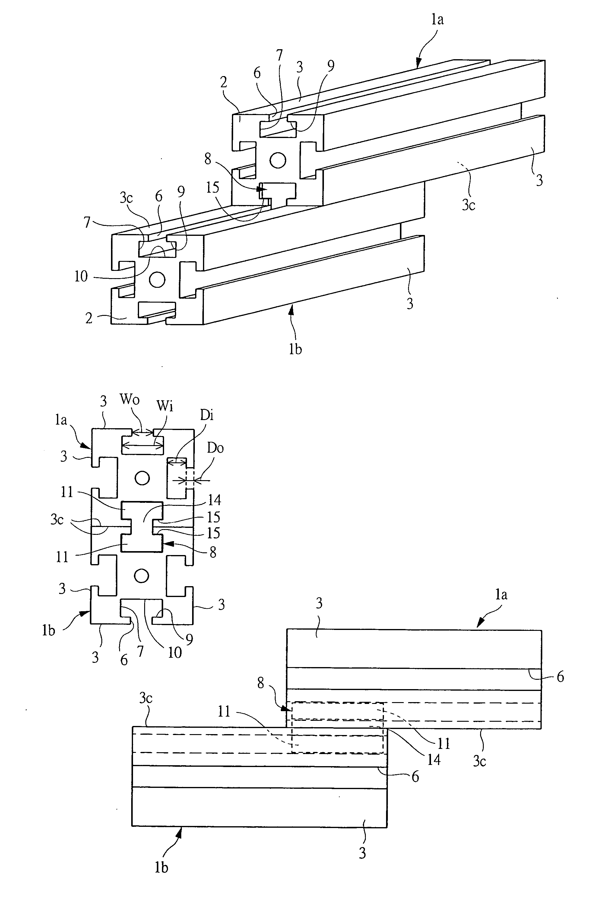
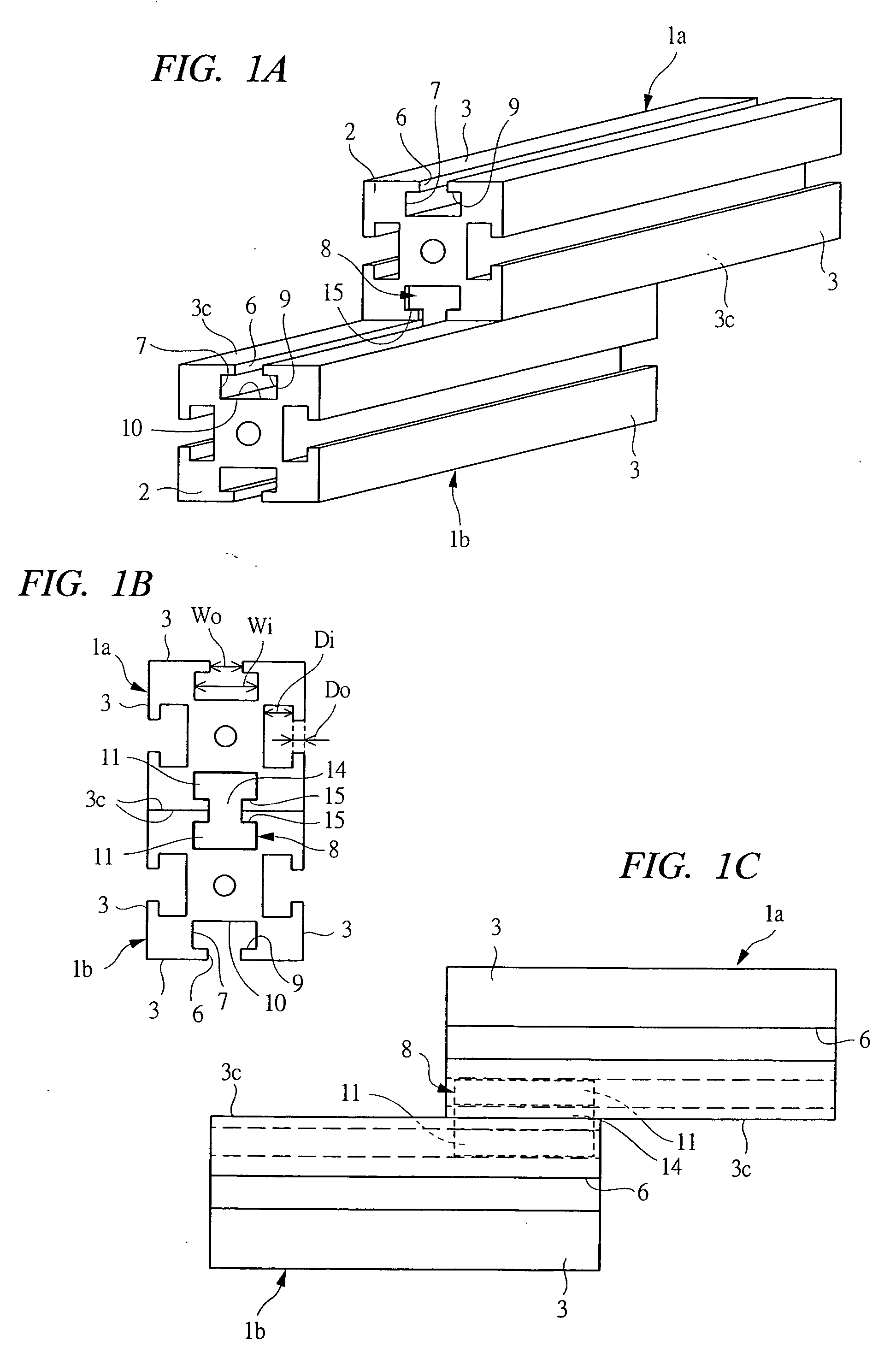
[0090] First, embodiments of a fastening assembly and a fastener will be explained. FIG. 1A is a perspective view showing two blocks fastened as a fastening assembly according to the present invention, FIG. 1B is a front view of the two blocks, and FIG. 1C is a side view thereof. As shown in FIG. 1, blocks 1a and 1b which are two members to be fastened are fastened at positions shifted in a longitudinal direction and in a state of contacting with each other.

[0091] Each of the blocks 1a and 1b, whose end faces 2 are regular tetragons, is formed into a cuboid, wherein a communication groove 6 opened and extending in the longitudinal direction and an engagement groove 7 communicating with it are formed in each of four side faces 3 thereof and wherein the communication groove 6 and the engagement groove 7 in each of connection surfaces 3c, which contact with each other, are fastened via an insertion fastener 8 serving as a fastener. The insertion fastener 8 becomes in a state in which a...

third embodiment

[0111]FIG. 7A is a perspective view of the entirety of an enlarging divided metal-fitting serving as a fastener used in a fastening assembly FIG. 7B is a front view of the enlarging divided metal-fitting installed in the interiors of the set of communication groove 6 and engagement groove 7 which are opposed to each other, and FIG. 7C is an insertion-directional cross-sectional view taken along line 7C-7C of FIG. 7B. In these Figures, members and shapes used in common with the fastening assembly shown in FIG. 5 are denoted by the same reference numerals.

[0112] As shown in FIG. 7, the enlarging divided metal-fitting 32 integrally has the two engaging pieces 11 which are disposed symmetrically in the vertical direction of the Figures, and the connecting portion 14 between the engaging pieces 11 is integrally formed therewith. At the central position in the vertical direction of the Figures, the coupling position 23 thereof is left on the thrust-directional side, and is divided mostly...

fourth embodiment

[0120]FIG. 9A is a perspective view of an entirety of a wedge dividing metal-fitting serving as a fastener used in a fastening assembly FIG. 9B is a front view of the wedge dividing metal-fitting installed in the fastened state in the interiors of one set of communication groove 6 and engagement groove 7 which are opposed to each other, FIG. 9C is a cross-sectional view taken along line 9C-9C of FIG. 9D, and FIG. 9D is an insertion-directional cross-sectional view taken along line 9D-9D of FIG. 9B. In these Figures, members and shapes common used in with the fastening assembly shown in FIG. 5 are denoted by the same reference numerals.

[0121] As shown in FIG. 9, the wedge dividing metal-fitting 46 is constituted so that two of a wedge metal-fitting 47 on the pull-directional side and a clamp metal-fitting 48 on the thrust-directional side (fastening pieces) are assembled in the insertion direction via a screw member. Each of the wedge metal-fitting 47 and the clamp metal-fitting 48 ...


PUM


Abstract

In a connection surface (3c) of each of two members (1a, 1b) to be fastened, a communication groove (6) opened on a surface and an engagement groove (7) communicating therewith, being wider than the communication groove (6), and provided with a connection surface (9) parallel to the connection surface (3c) are formed. A fastener (8) includes: two engaging pieces (11), which can be inserted into the engagement grooves (7) and are wider than the communication grooves (6) and are provided with fastening surfaces (15); and a connecting portion (14) therebetween, wherein the entirety of the fastener (8) can be inserted into the interior of one set of communication groove (6) and engagement groove (7), which are opposed to and communicate with each other, by thrusting the respective engaging pieces (11) and connecting portion (14) thereto. In the inserted state, fastening surfaces (15) of the respective engaging pieces (11) contact with engagement surfaces (9) of the engagement grooves (7), thereby being unable to be pulled out in a direction orthogonal to the connection surfaces (3c) of the two members (1a, 1b). That is, the two members (1a, 1b) have nothing protruding from a surface by virtue of the fastening assembly, and are in a firmly fastened state via the fastener (8).

Description

TECHNICAL FIELD [0001] The present invention relates to a fastening assembly and a fastener for fastening two members to each other, and to a fluid pressure cylinder unit fastened and assembled with an attachment by the fastener assembly and the fastener. BACKGROUND ART [0002] Conventionally, a fastening means for attachably and detachably coupling a plurality of members or parts to one another includes mainly a fastening metal-fitting such as a bolt having a screw, or a pin or cotter utilizing a wedge action, elasticity, or friction. [0003] Also, a fastening means other than one employing the above-described fastening metal-fitting includes, for example, as described in Japanese Patent Laid-Open Publication No. 8-128420, a structure in which: a T-slot is formed in each of connection surfaces of two members to be fastened; a linking member, in which a pair of protrusions and a pair of elastic protrusions are symmetrically formed on a center wall regarded as a center, is used; the pr...

Claims


Application Information

Patent Timeline
Patent Type & Authority Applications(United States)
IPC IPC(8): E21B17/046B23Q1/58F15B13/00F15B13/08F15B15/08F15B15/14F16B7/02F16B7/04F16B7/18F16B13/08
CPCB23Q1/58F15B13/0817F15B13/0821F15B13/0839Y10T403/61F15B15/1404F16B7/025F16B7/0433F16B13/0891F15B15/082
Inventor HARASHIMA, YASUONAKAJIMA, YOSHIAKIGUNJI, HIROSHI
Owner KOGANEI
Why Eureka
Try Eureka