Implant device and method

Inactive Publication Date: 2006-06-22
WOHL ISHAY
View PDF0 Cites 50 Cited by
  • Summary
  • Abstract
  • Description
  • Claims
  • Application Information

AI Technical Summary

Benefits of technology

[0024] The present invention suggests a device and method to install and attach an

Problems solved by technology

A problem with such devices is a possible movement of the implant over time.
Such solutions have proven unsatisfactory.
The implant devices today are known to be unstable, for example the breast implants can rotate, move

Method used


Image

  • Implant device and method
  • Implant device and method
  • Implant device and method

Examples


Embodiment Construction

[0043] A preferred embodiment of the present invention will now be described by way of example and with reference to the accompanying drawings.

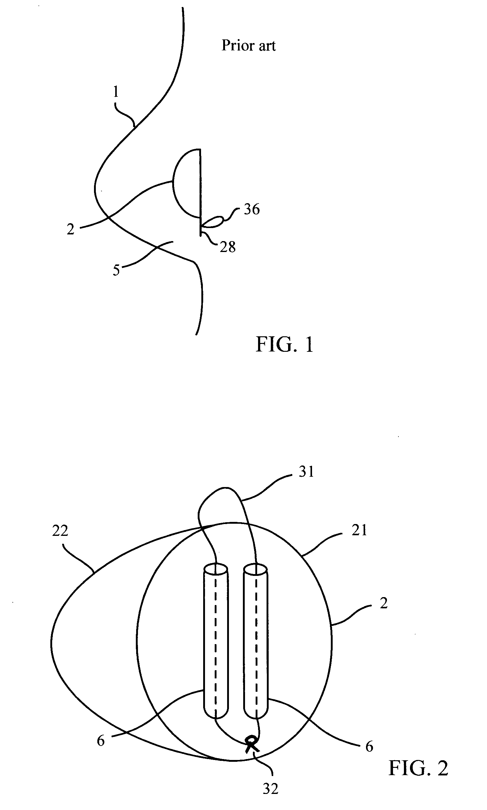
[0044]FIG. 1 illustrates a fixing method used in prior art.

[0045] An implant device 2 is installed in the woman breast 1 through a cut 5 performed at its lower part.

[0046] A surgical wire 36 may be used to attach plate 28 of the implant 2 to chest wall and / or muscles.

[0047] The plate 28 is part of the implant 2 and is located in its lower part as illustrated.

[0048] A disadvantage of such prior art device and method is that it may not be effective in preventing the implant 2 from rotating sideways or forward, because of its location. The implant may be unstable mechanically.

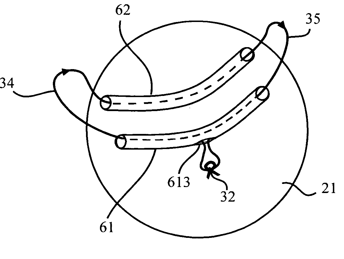
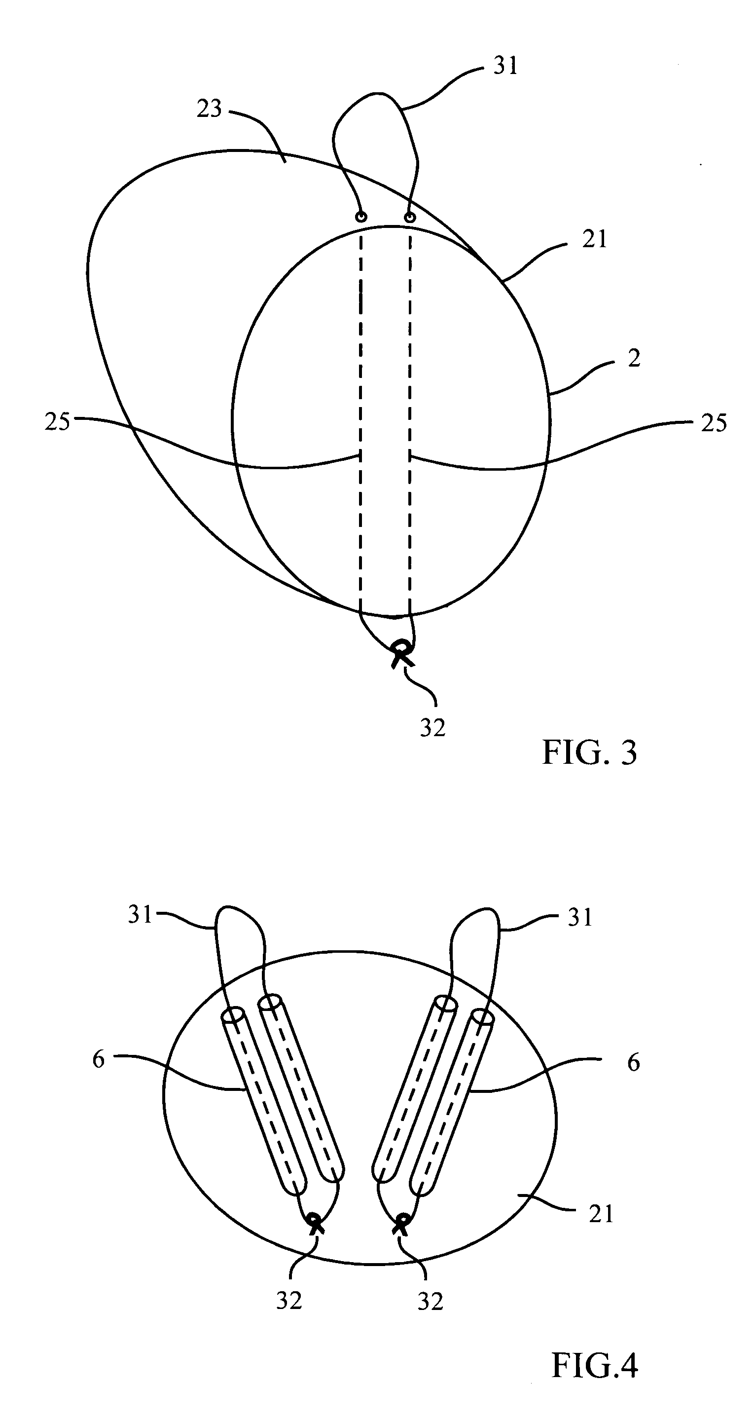
[0049]FIG. 2 illustrates an implant device 2 with means for securing it to the body at its upper part, using a surgical wire loop 31. The surgical wire passes through the two tubes 6 on the implant 2.

[0050] The tubes 6 are made of a flexible material which is not com...


PUM


Abstract

A breast implant includes means for attaching to a patient's body at an attaching point located at the upper part of the implant using surgical wire, and for allowing to secure the wire at a securing point located on the lower part of the implant. The means for attaching to a patient's body further include two flexible noncompressible tubes for passing the surgical wire up to the attaching point, and back down to the wire securing point. The means for attaching to a patient's body further include two pairs of flexible noncompressible tubes for passing the surgical wire up to the attaching point, and back down to the wire securing point.

Description

CROSS-REFERENCE TO RELATED APPLICATIONS [0001] The present application claims priority from the patent application No. GB0427930.3 filed in Great Britain by the present inventor on Dec. 21, 2004 and entitled “Implant device and method”. FIELD OF THE INVENTION [0002] The present invention relates to breast implant devices and methods, and more particularly to such implants with improved means for attaching to the human body. BACKGROUND OF THE INVENTION [0003] At present, breast implant devices usually made of silicon gel or saline filled bags are planted in a woman's breast for cosmetic breast augmentation and / or breast reconstruction. [0004] These breast implants, after being placed there by the surgeon, are usually held in place by body tissue, such as the breast skin and tissue, or the chest muscles. [0005] A problem with such devices is a possible movement of the implant over time. Such movement may be caused by body movement, gravity (the weight of the device) and the fact that ...

Claims


Application Information

Patent Timeline
IPC IPC(8): A61F2/12
CPCA61F2/12
Inventor WOHL, ISHAY
Owner WOHL ISHAY
Why Eureka
Try Eureka