
Method for correcting control surface angle measurements in single viewpoint photogrammetry

a single-point angle and measurement method technology, applied in the field can solve the problems of significant wing bending-induced bias error, affecting the accuracy of single-point angle measurement, so as to minimize the difference between the reference and apparent distance

Inactive Publication Date: 2006-06-22
NAT AERONAUTICS & SPACE ADMINISTATION ADMINISTATOR OF THE UNITED STATES OF AMERICA AS REPRESENTED BY THE
View PDF12 Cites 33 Cited by
  • Summary
  • Abstract
  • Description
  • Claims
  • Application Information

AI Technical Summary

Benefits of technology

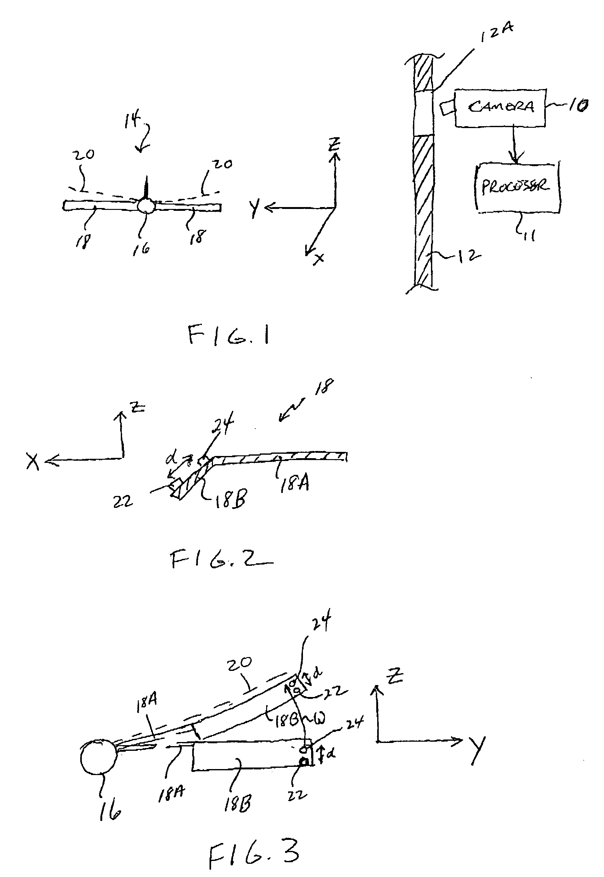
The present invention provides a method for determining the angle of a control surface on an aircraft wing during wind on conditions using single viewpoint photogrammetry. The method involves positioning two targets on the control surface at a distance from each other and at a semispan distance along the aircraft wing. The targets are then moved by the air flow over the wing, causing the wing to bend through an angle. The apparent distance between the targets is measured, and a corrected semispan distance is determined to minimize the difference between the reference and apparent distances. The final solution includes a corrected difference in the Z-direction and a corrected difference in the X-direction. The corrected angle is defined by tan−1 ((ΔZ/cos ω)/ΔX)). This method allows for accurate determination of the angle of the control surface during wind on conditions.

Problems solved by technology

The patent text describes a technique for measuring flow-induced wing twist and control surface deformation in wind tunnel environments for aircraft models and in-flight for actual aircraft. The technique uses a single camera and a processor to implement single viewpoint photogrammetric computations. However, the problem is that the Y-coordinate of the targets on the control surface changes as the wing bends during a wind on condition, resulting in significant error in the generated solutions. The patent proposes a solution to mitigate this issue.

Method used


Image

  • Method for correcting control surface angle measurements in single viewpoint photogrammetry
  • Method for correcting control surface angle measurements in single viewpoint photogrammetry
  • Method for correcting control surface angle measurements in single viewpoint photogrammetry

Examples


Embodiment Construction

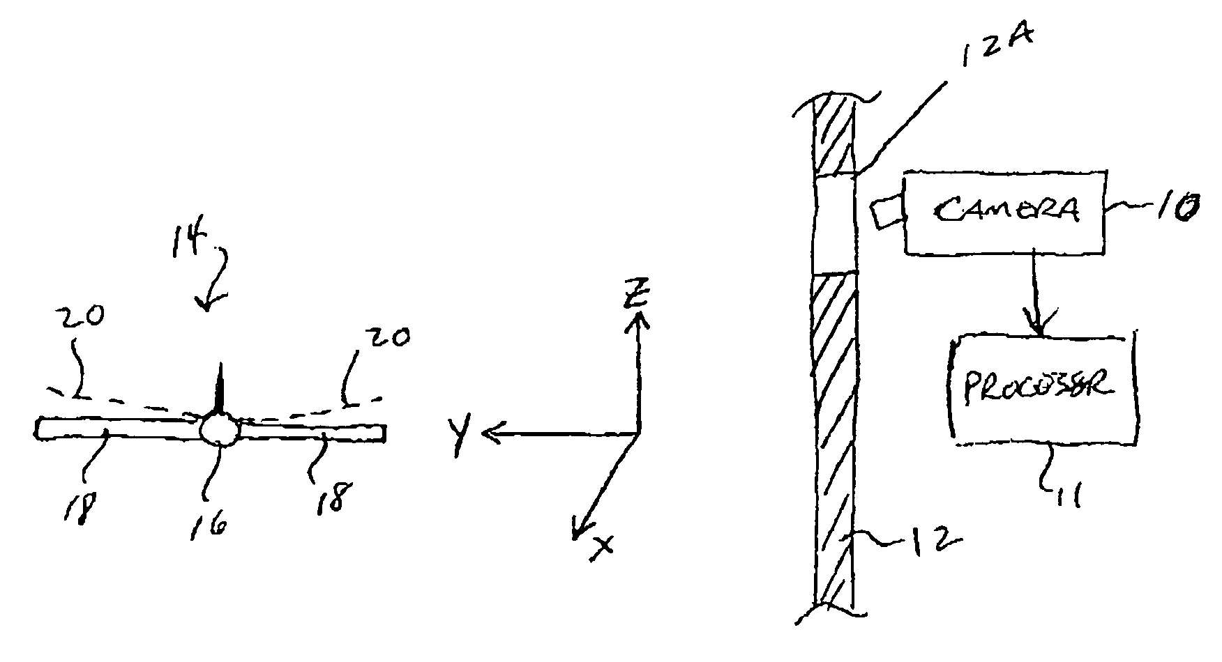
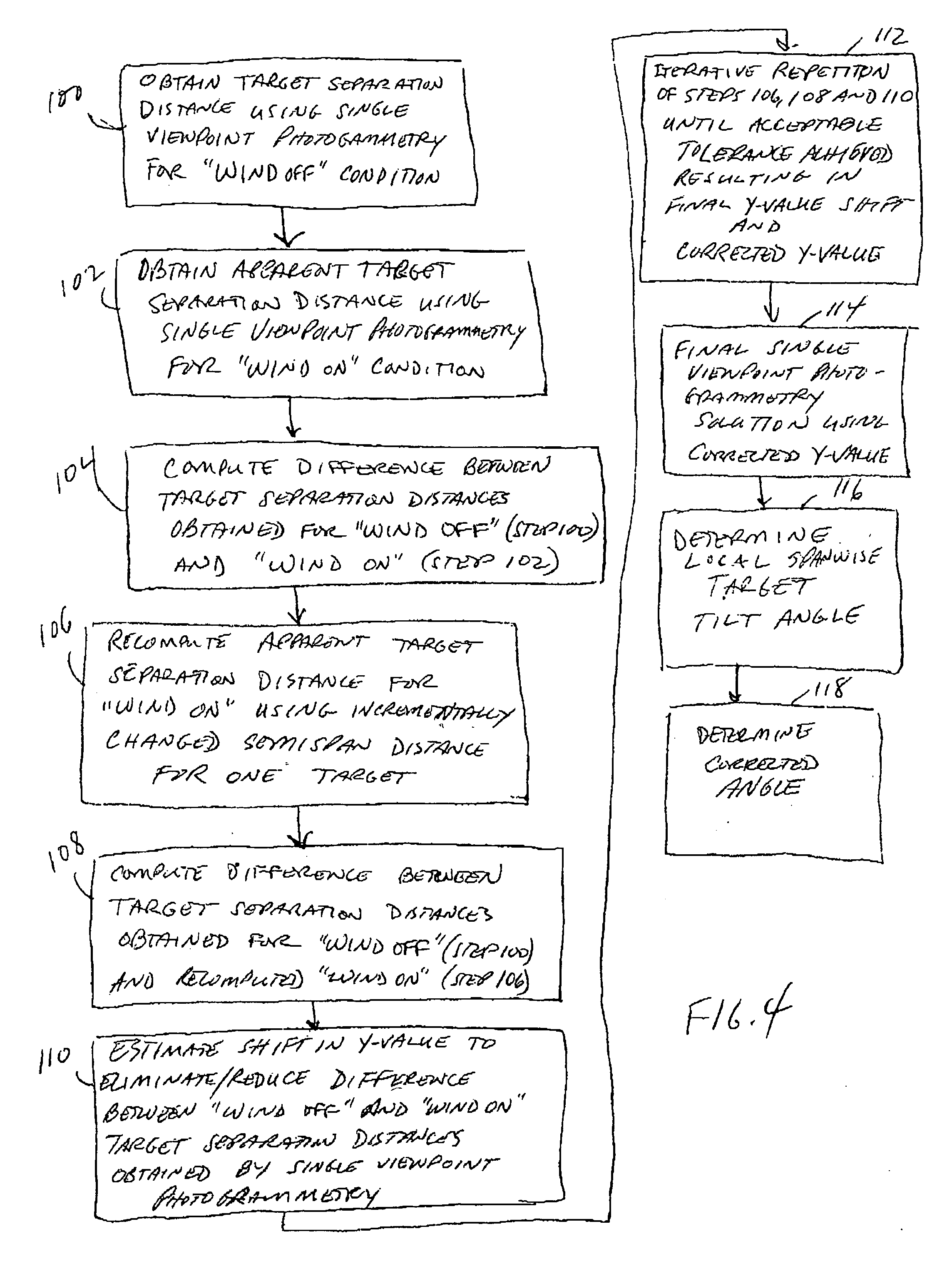
[0021] The present invention is a method of correcting wing bending-induced bias error introduced into single viewpoint photogrammetric computations used to determine control surface angular deformation. To explain the method of the present invention, continued reference will be made to FIGS. 1-3 while simultaneously referring to the flow chart in FIG. 4. It will be assumed for this illustration that in a “wind off” condition, targets 22 and 24 on control surface 18B are aligned in the Y-dimension. That is, targets 22 and 24 are located at the same semispan distance from fuselage 16 during “wind off”. As used herein, the phrase “wind off” is defined as no wind flowing over aircraft 14 whereas the phrase “wind on” means that there is air moving in the X-dimension over aircraft 14.

[0022] The first step (i.e., step 100 in FIG. 4) in the present invention is to utilize camera 10 and processor 11 to generate a single viewpoint photogrammetric solution that includes a measure of the sepa...


PUM


Abstract

A method of determining a corrected control surface angle for use in single viewpoint photogrammetry to correct control surface angle measurements affected by wing bending. First and second visual targets are spaced apart from one another on a control surface of an aircraft wing. The targets are positioned at a semispan distance along the aircraft wing. A reference target separation distance is determined using single viewpoint photogrammetry for a “wind off” condition. An apparent target separation distance is then computed for “wind on.” The difference between the reference and apparent target separation distances is minimized by re-computing the single viewpoint photogrammetric solution for incrementally changed values of target semispan distances. A final single viewpoint photogrammetric solution is then generated that uses the corrected semispan distance that produced the minimized difference between the reference and apparent target separation distances. The final single viewpoint photogrammetric solution set is used to determine the corrected control surface angle.

Description


Claims


Application Information

Patent Timeline
Owner NAT AERONAUTICS & SPACE ADMINISTATION ADMINISTATOR OF THE UNITED STATES OF AMERICA AS REPRESENTED BY THE
Learn More