Method for modeling detection of camouflaged targets

a camouflage target and detection method technology, applied in the field of camouflage target detection methods, can solve the problems of inability to accurately model the range at which low thermal contrast targets are detected, and inability to accurately model the range of camouflage targets

Inactive Publication Date: 2006-06-22
ARMY UNITED STATES OF AMERICA AS REPRESENTED BY
View PDF2 Cites 18 Cited by
  • Summary
  • Abstract
  • Description
  • Claims
  • Application Information

AI Technical Summary

Problems solved by technology

The ACQUIRE model, however, suffers from certain limitations.
Specifically, camouflaged and reduced signature targets have long presented problems for modeling target acquisition performance, and the ACQUIRE model loses integrity when the target is thermally camouflaged.
Stated differently, the ACQUIRE method for comparing sensor performance is relatively insensitive to target temperature contrast, and field studies have determined that the ACQUIRE method generally overestimates the range at which low thermal contrast targets are detected.
This inaccuracy in prediction modeling has hampered the evaluation of camouflage effectiveness, and it hinders the development of engagement tactics for various weapons systems.
If N50 is increased too much, an underestimation of sensor performance results.
Conversely, if the ACQUIRE methodology described above is used to predict the detection range of a thermally camouflaged target, an inaccurate prediction results.
A further disadvantage of requiring special test and / or analyses for each situation is that it leads to great inefficiencies and long delays associated with acquiring appropriate data for use in estimating lower contrast target performance.

Method used


Image

  • Method for modeling detection of camouflaged targets
  • Method for modeling detection of camouflaged targets
  • Method for modeling detection of camouflaged targets

Examples


Embodiment Construction

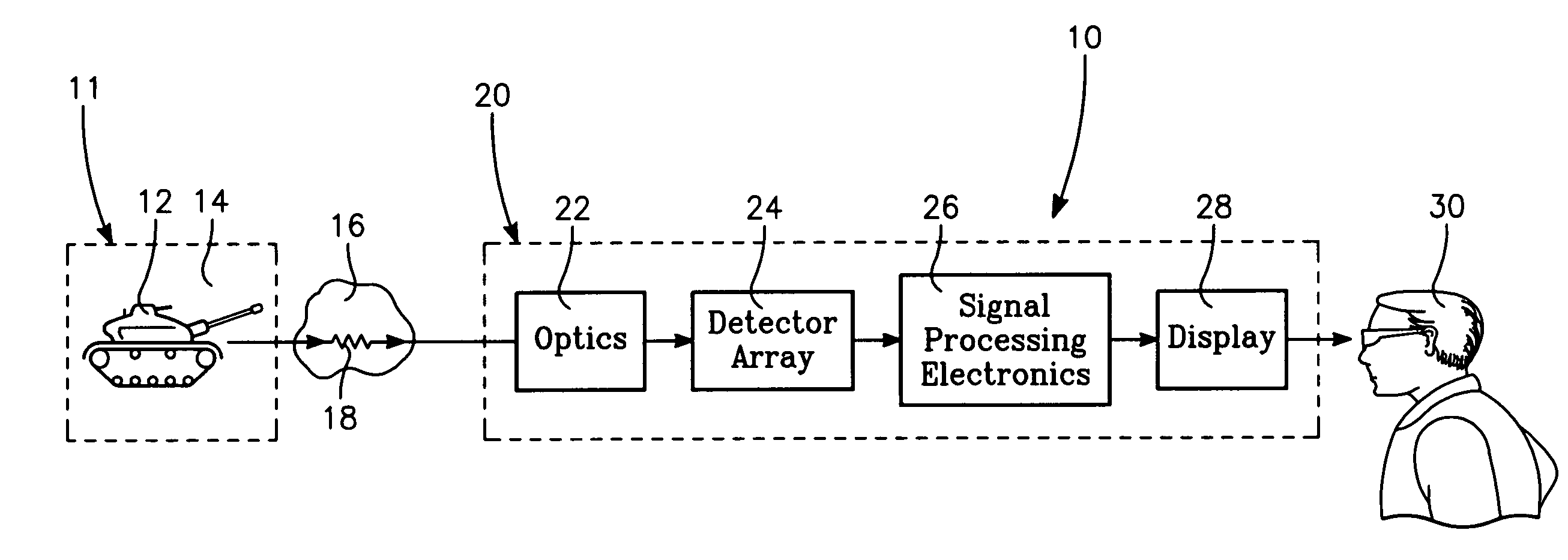
[0018] By way of background, and referring initially to FIG. 1, a simplified diagram of image chain 10 that illustrates the important components of target acquisition problem is presented. As shown, the radiance 18 from the scene 11 is a complex function of thermal radiance from target 12 and the immediate background thereof 14, with the nature of the complex function described in greater detail below. The emitted or reflected radiation 18 passes through the atmosphere 16, where some of the radiance is absorbed or scattered. Background radiation can also be scattered into the same path toward the imaging system.

[0019] After passage through the atmosphere as described above, radiation 18 is received by imaging system 20. Within imaging system 20, optics 22 gather the radiation and form an image of the scene at the image plane of the system. A single detector 24 (or an array of single detectors 24) samples the incident radiation. The image can be sampled in various ways: A single det...


PUM


Abstract

The methods for determining the probability of detection of a thermally camouflaged target at various ranges by the sensor includes determining an “inherent” temperature difference, ΔTRSS, between the target and its immediate surroundings. Once ΔTRSS is determined, a scaled N50 cycle criterion, or the number of resolvable cycles needed by the sensor for a fifty percent probability of detection, is determined according to the relationship N50=A / (ΔTRSS)B+C, where A, B and C are constants that are predetermined according to whether the immediate surroundings are of a woodland or a littoral nature. The scaled N50 cycle criterion is then used in an empirical Target Transfer Probability Function (TTPF) defined by P=(N / N50)E / (1+(N / N50)E), where E=2.7+0.7(N / N50), in order to determine the probability of detection of the thermally camouflaged target.

Description

GOVERNMENT INTEREST [0001] The invention described herein may be manufactured, used, sold, imported, and / or licensed by or for the Government of the United States of America.FIELD OF THE INVENTION [0002] The present invention applies generally to methods for modeling sensor performance. More particularly, the present invention applies to an analytical method for predicting the detection of a camouflaged target by systems that image in the mid- and far-infrared spectral bands. BACKGROUND OF THE INVENTION [0003] Accurate predictions of electro-optical imager performance (in terms of the range at which the imager will detect a target) are important for several reasons. The predictions serve as a guide for system development by providing a means for comparing different systems while still in their design phase, and they can be used to decide if systems with a specific design will meet established requirements. The predictions are also used in war game simulations that directly influence...

Claims


Application Information

Patent Timeline
Patent Type & Authority Applications(United States)
IPC IPC(8): G06F17/18
CPCG06K9/3241H04N5/33G06V10/255
Inventor O'KANE, BARBARA L.PAGE, GARY L.WILSON, DAVID L.
Owner ARMY UNITED STATES OF AMERICA AS REPRESENTED BY
Why Eureka
Try Eureka