

Broadcasting signal receiving system
- Summary
- Abstract
- Description
- Claims
- Application Information
AI Technical Summary
Benefits of technology
Problems solved by technology
Method used
Image

Examples
Embodiment Construction
[0026] Now, embodiments of the present invention will be described below by referring to the drawings.
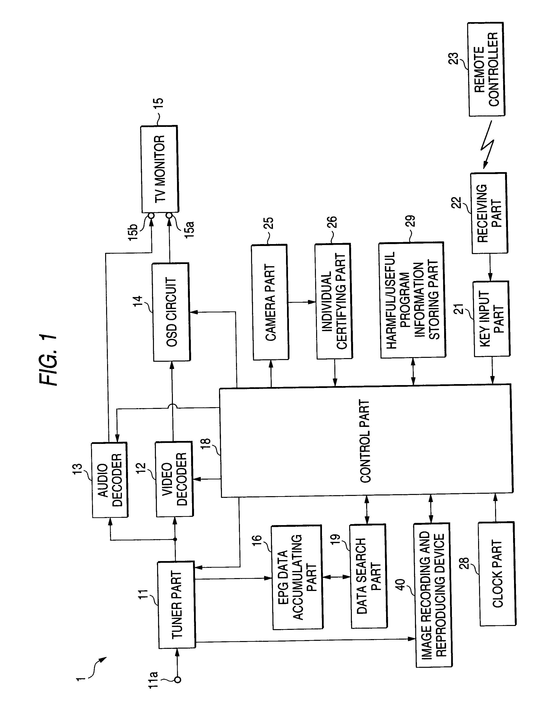
[0027]FIG. 1 is a functional block diagram showing the entire structure of a broadcasting signal receiving system of the present invention.
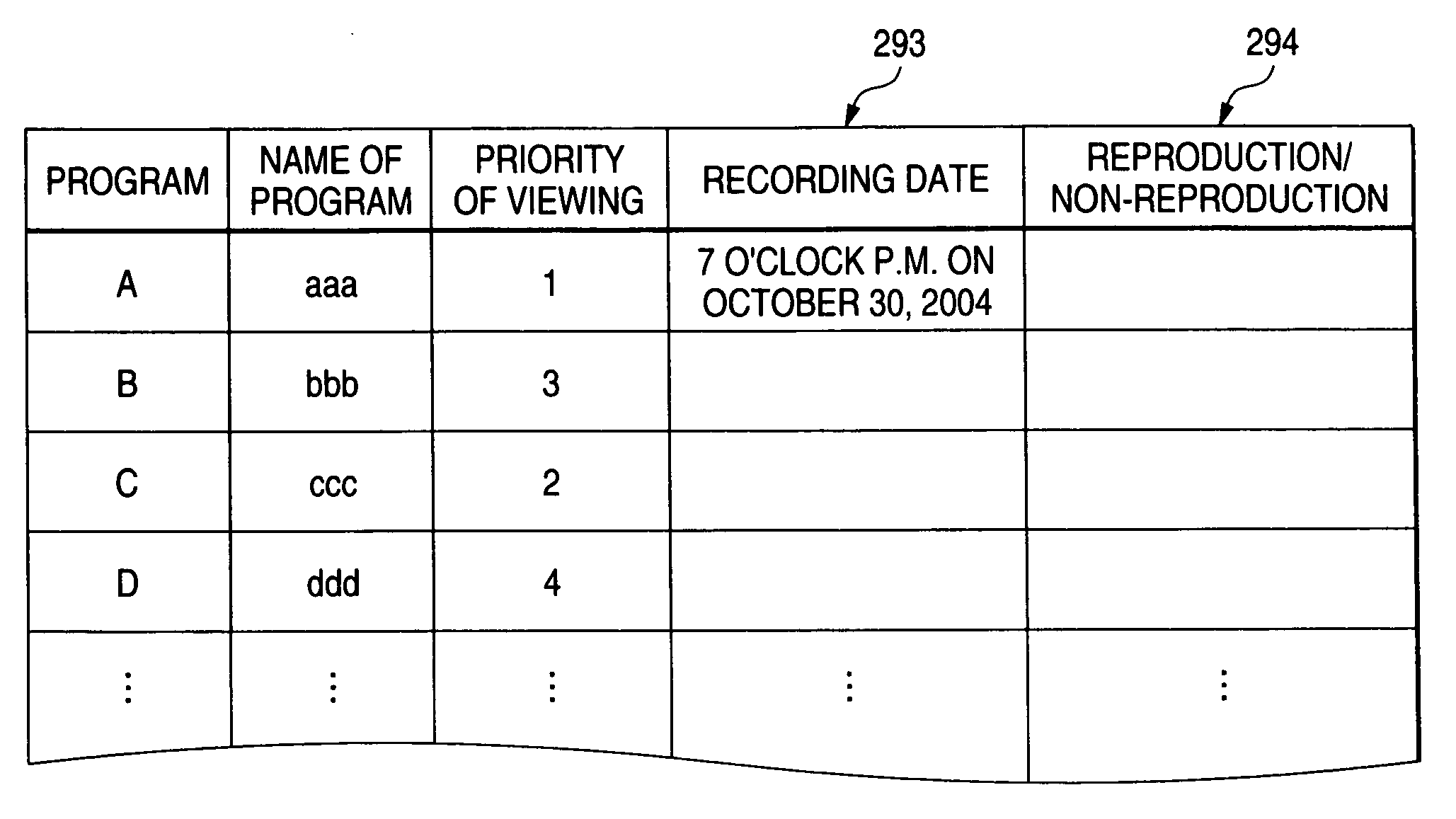
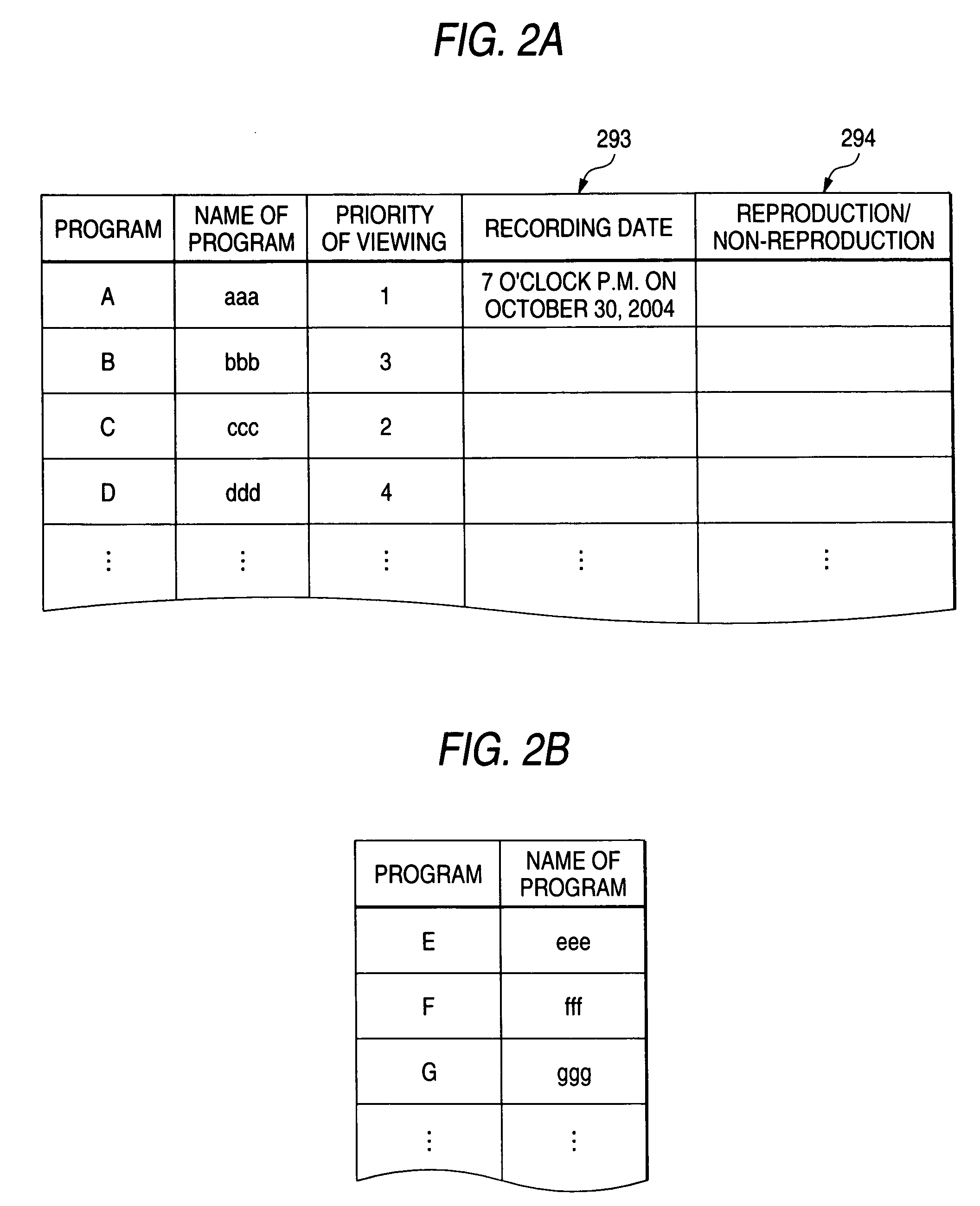
[0028] A broadcasting signal receiving system 1 includes an input terminal 11a for inputting a broadcasting signal received by an antenna not shown in the drawing and a tuner part 11 is connected to the input terminal 11a. An output of the tuner part 11 is connected to a video decoder 12 for converting a digital video signal to an analog video signal and connected to an audio decoder 13 for converting a digital audio signal to an analog audio signal. Further, the output of the video decoder 12 is connected to a video input terminal 15a of a TV monitor 15 through an OSD (on screen display) circuit 14. Further, the output of the audio decoder 13 is connected to an audio input terminal 15b of the TV monitor 15.
[0029] Further, a received broadcast...
PUM
 Abstract
Description
Claims
Application Information